
Fire Prevention and Fire Fighting
Fire fighting bulk $\displaystyle \small \mathrm{CO_2}$
$\displaystyle \small \mathrm{CO_2}$ Calculation
$\displaystyle \small \mathrm{CO_2}$ flooding procedure
Fire Detection
Foams desirable properties
Types of foams
Important thing to consider in liquid fire
Special type of foam
Working principles of fire detection
Maintenance and inspection for fire protection systems
$\displaystyle \small \mathrm{CO_2}$ system checks and maintenance
Fire safety objectives:1. Prevent the occurrence of fire and explosion.2. Reduce the risk of loss of life caused by fire on ships.3. Reduce the risk of damage caused by fire to the ship, Its cargo and the environment.4. Contain, control and suppress fire and explosion in the compartment of origin.5. Provide adequate and readily accessible means of escape for passengers and crew.Functional requirements:1. Division of the ship into main vertical and horizontal zones by thermal & structural boundaries.2. Separation of accommodation spaces from the remainder of the ship by thermal & structural boundaries.3. Restriction on the use of combustible materials.4. Detection of any fire in the zone of origin.5. Containment of any fire in the space of origin.6. Protection of means of escape and access for fire fighting.7. Make fire extinguishing appliances readily available.8. Minimize the possibility of flammable cargo vapor ignition.What is combustion?Combustion is a chemical reaction or series of reactions, in which heat and light are evolved.In a slow reaction only heat is evolved and oxidation occurs.In a rapid reaction heat as well as light emits.Remove any part of the triangle and combustion stops.Fire/Combustion Triangle
The fire triangle or combustion triangle is a simple model for understanding the necessary ingredients for most fires.
The triangle illustrates the three elements a fire needs to ignite: heat, fuel, and an oxidizing agent (usually oxygen).
A fire naturally occurs when the elements are present and combined in the right mixture.
A fire can be prevented or extinguished by removing any one of the elements in the fire triangle. For example, covering a fire with a fire blanket blocks oxygen and can extinguish a fire.Fire Tetrahedron
The fire tetrahedron represents the addition of a component in the chemical chain reaction, to the three already present in the fire triangle. Once a fire has started, the resulting exothermic chain reaction sustains the fire and allows it to continue until or unless at least one of the elements of the fire is blocked.

Fire tetrahedron illustrates how combustion is supported & sustained throughout the chain reaction.
Modern extinguishing agents directly attack & breakdown chain reactions
Chain reaction (the 4th element represents a continuous burning fire)

Factors involved in combustion: (A). Flash Point: Flashpoint is the lowest temperature at which a liquid can gives off vapour to form an ignitable mixture in air near the surface of the liquid. (B). Fire Point: Fire point refers to the temperature at or above which a flammable liquid produces enough vapour to ignite by spark or flame and combustion continues. (C). Auto-Ignition Temperature: It is the lowest temperature at which the fuel will spontaneously ignite in a normal atmosphere without an external source of ignition such as a flame or spark. STOICHIOMETRIC Mixture: One molecule of methane reacts with two molecules of oxygen gas to yield one molecule of carbon dioxide and two molecules of water. This particular chemical equation is an example of complete combustion. Air-only contains 20% oxygen. Air to methane ratio 10:1 This means 90.9% of air with 9.1% methane is called Stoichiometric mixture for combustion of methane in the air, which produce the highest flame temperature.

Limits of flammability:
The highest and the lowest concentration at which combustion can occur are known as the range of flammability.
Lower flammability limit (LFL): The lowest concentration (percentage) of a gas or a vapour in air capable of producing a flash of fire in the presence of an ignition source (arc, flame, heat). For methane – 5%
Upper flammability limit (UFL): Highest concentration (percentage) of a gas or a vapour in air capable of producing a flash of fire in the presence of an ignition source (arc, flame, heat). For methane – 16%

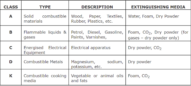
Classification of fire:

Fire detection in holds and in accommodation
Q. Fire detection in holds and in accommodation?Fire fighting bulk $\displaystyle \small \mathrm{CO_2}$
Fire fighting bulk $\displaystyle \small \mathrm{CO_2}$
$\displaystyle \small \mathrm{CO_2}$ H.P multi-cylinder type total flooding system is operated by using gas pressure. The operator in the control potion releases the gas from pilot cylinder in the $\displaystyle \small \mathrm{CO_2}$ room by means of a manual pull wire.
The $\displaystyle \small \mathrm{CO_2}$ from the cylinders act on the pistons of a gas release system. Movement of the piston actuates a series of levers attached to the cylinder head valves which by means of special cutter releases the gas to the manifold. The released gas then passes to a control valve at the control station and hence to the different heads in the protected space.
(a) Control cabinet door cannot be closed with control valve in open position.
(b) concise instruction must be provided at control position.
(c) Control cabinet door locked, key kept in glass box adjacent to control cabinet with a special hammer to shatter the glass attached.
$\displaystyle \small \mathrm{CO_2}$ Calculation
Calculationcylinder details:- Material - manganese steel
$\displaystyle \small \mathrm{CO_2}$ Contain - 45.4 kg
Cyl. Capacity - 68 litres
Filling Ratio - 0.67
Empty Cyl weight - 80 kg
Safety disc bursting pressure - 190 bar @ 63 deg cel.
Storage pressure - 52 bar @ 15 deg cel.
Test pressure - 250 bar
volume of free $\displaystyle \small \mathrm{CO_2}$ = 0.56 cubic meter per kg.
E.R gross volume = X without casing 40%
E.R gross volume = Y with casing 35%
Volume of free air bottles = Z
Volume of maximum cargo hold = A
As per regulation No. of bottle:-
E/R without casing $\displaystyle \small \mathrm{\frac{(X+Z)\times 0.40}{0.56\times 45.4}}$
E/R with casing $\displaystyle \small \mathrm{\frac{{(Y+Z)\times 0.35}}{0.56\times 45.4}}$
largest cargo hold $\displaystyle \small \mathrm{\frac{{A\times 0.3}}{0.56\times 45.4}}$
*Casing:- Horizontal area 40% or less of midway horizontal area between Tank top and lower casing part.
Z can be omitted in air bottle relief valve bursting disc discharge goes outside protected space
$\displaystyle \small \mathrm{CO_2}$ flooding procedure
$\displaystyle \small \mathrm{CO_2}$ flooding procedure(a) chief engineer to take charge of the operation.
(b) ETO to start emergency generator and put on load. Electric circuit to engine room from emergency switch board to be isolated.
(c) Activate the $\displaystyle \small \mathrm{CO_2}$ release alarm by opening control box door. It will trip E/R vent fans, purifier space exhaust, main engine auxiliary blower, engine control room A/C and power panel.
(d) All person report to muster station, ensure all engine room entrance are shut while leaving E/R and also on all decks in accommodation.
(e) take a head count and ensure all present or accounted for.
(f) confirm remote stop activated.
(g) 2nd engineer to trip all quick closing valves.
(h) 3rd engineer to start emergency fire pump and ensure proper operation and standby, confirm Isolating valve to E/R shut.
(i) Support squad to close all blower flaps, funnel flaps, skylight, All engine room and funnel doors.
(j) emergency squad to start boundary cooling as required.
(k) confirm engine room is sealed and final head count.
(l) Inform master and discharge $\displaystyle \small \mathrm{CO_2}$.
Fire Detection
Photoelectric smoke detectors.Ionization smoke detectors.
Foams desirable properties
Used as liquids whose density is less than water. It removes the oxygen face of fire Tetrahedron.Desired qualities are
(a) cohesion- tough bubble
(b) vapour suppression- suppressing flammable or toxic vapours.
(c)stability/ water retention - to perform cooling
(d) heat resistance - resistance to radiate heat.
(e)flowability - must flow freely.
(f) fuel resistance- should not get saturated with fuel.
(g) chemical resistance - resistance to detrimental chemical effect
Types of foams
(a) Protein form (hydraulised protein) - low cost but slow flow. Decomposition of protein such as loaf, hornmeal, chicken feather, blood and mineral salts.
(b) Fluoro protein foam:- it is the cheapest of all and general purpose foam, comound of fluorine added to imrove flow, flame resistance, super sealing and extinguishing properties.
(c) Synthetic foam - mixture of water soluble surface active agents desired from hydrocarbons ( fluoro carbons with additional stabilisers) it has a batter flow and same expension as of protein foam but a poor flame resistance and have tendency to mix with fuel.
(d) Fluorochemical foam( Aqueous film forming foam), AFF- It is produced from a combination of fluorocarbon surfactants and stablizers. They produce more fluid then protein and fluoro-protien foam, Fast drainage rate. Liquid draining out floats on the fuel surface as "light water" have an effective sealing capacity, have reasonable burn back resistance. do nmot provide long term vapour suppression. Do not have good chemical resistance. Low surface tension, so foam spreads rapidly. suitable for both portable extinguishers and combating major oil tanker fire.
(e) Film forming fluroprotiein foam (FFFP):- it is a film forming combination of protein and fluorinated surface activae substances and stabilisers with similar properties as of AFFF but with better knock down and burn back properties.
(f)Alcohol resistance foam:- A polymer ingredient is added to the foaming agent (protein or luoroprotein) and a stabiliser which form a fuel insoluble membrane at the interface between the liquid and the foam. The separating membrane prevents the destruction of the foam. Various types of synthetic protein foam as well as AFFF and FFFP type alcohol resistance foams are available, they are suitable for chemical cargo
(g) High expension foam - the expansion ratio is 1000:1 the foaming agent include ammonium lauryl sulphate and sodium dodecyl benzeze sulphate. It comprises a fan which force air through a mesh screen.
Important thing to consider in liquid fire
Theory of oil combustionThe burning area of oil tank usually can be divided into three layers, fire layer, mixture layer of air and flammable vapor and oil liquid layer.
In oil combustion, the negative pressure will occur at certain area because of consumption of oxygen and it inhales surrounding cold air into this area, which will mix with flammable vapor and form mixture layer. The existence of mixed layer makes the flame wave and its combustion rate gradually tends to a constant value. The mixed layer is influenced by diffusion velocity of surface vapor, in other words that the diffusion velocity of surface vapor determines the process of combustion.
In the process of combustion, part of heat diffuses to the outside through the thermal radiation and heat convection when others feedbacks to the surface of oil through heat conduction of tank wall, heat convection of hot smoke and thermal radiation of flame. It keeps flammable vapor producing steadily from surface and propels combustion. Combustion of vapor, heat feedback and evaporation are three related and circulatory links and only intervene this loop and slow its process, the combustion could be stopped.
Analysis of difficulty in suppressing oil tank fire
(1) The strong airflow will occur in oil tank fire. The characteristics of the flame are closely related to diameter of the tank, the nature of the liquid and liquid level. When the liquid level is high, the flame is torch-like shape and cold air enters combustion area from sides. With the combustion, the cold air will rise as well as mix with vapor through the centre of liquid surface when the liquid level decreases to 80%. By this time, the rising airflow blows part of lightweight foam and it causes the foam is hard to adhere to the surface.
In addition to the airflow, the bad wind weather could also form resistance to jet foam and will blows the foam adhered to surface, which causes loss of effective foam. In order to solve the above problems, heavyweight and high-injection pressure foam is needed. At the same time, producing more foam can has effect under certain provided condition.
(2) In oil tank fire, there are high temperature and long suppressing time. The flame temperature is above 1000 deg cel. in continuous oil tank fire. When the foam doesn’t completely cover the oil surface, the gas inside foam will break the foam because of thermal expand. The high temperature will reduce viscosity of liquid which distribute between foam films and promote the liquid withdrawal rate. When the foam doesn’t completely cover the oil surface, the oil tank is still in state of high temperature which could promote the evaporation. A channel will be formed when vapor rises through foam layer. It will break the airtightness of foam layer and induces the oil rekindle. These problems both can weaken the performance of foam. Based on the above analysis, the efficiency of suppressing fire can be increased by using the foam which has good burn resistance and long drainage time. In addition, if the foam covered on the surface is thick, this problem also can be relieved.
Special type of foam
Alcohol Resistance form:-A polymer ingredient is added to the foaming agent (protein or fluoro-protein) and a stabiliser which form a fuel insoluble membrane at the interface between the liquid and the foam. This separating membrane prevents the destruction of the form. various types of synthetic protein foam as well as AFFF & FFFP types alcohol resistance foams are available. Suitable for chemical cargo.
Working principles of fire detection
Three basis working principles of fire detectionSmoke, heat and flame detection
Maintenance and inspection for fire protection systems
Minimum level of maintenance and inspection for fire protection systems and appliances onboard.As required by the International Maritime Organization which are intended to ensure that fire systems are kept in good working order as specified in SOLAS Regulation II-2/14.2.1.2.
Certain maintenance procedures and inspections may be performed by competent crew members, while others should be performed by persons specially trained in the maintenance of such systems.
3. Weekly testing and inspections:-
(b). Fixed gas fire-extinguishing systems :- verify all fixed fire-extinguishing system control panel indicators are functional by operating the lamp/indicator test switch; and verify all control/section valves are in the correct position.
(c). Fire doors :- verify all fire door control panel indicators, if provided, are functional by operating the lamp/indicator switch.
(d). Public address and general alarm systems :- verify all public address systems and general alarm systems are functioning properly.
(e). Breathing apparatus :- examine all breathing apparatus and EEBD cylinder gauges to confirm they are in the correct pressure range.
(f). Low-location lighting :- verify low-location lighting systems are functional by switching off normal lighting in selected locations.
(g). Water mist, water spray and sprinkler systems :- verify all control panel indicators and alarms are functional; visually inspect pump unit and its fittings; and check the pump unit valve positions, if valves are not locked, as applicable.
4. Monthly testing and inspections :- Monthly inspections must be carried out to ensure that the indicated actions are taken for the specified equipment.
(a). Fire mains, fire pumps, hydrants, hoses and nozzles :- verify all fire hydrants, hose and nozzles are in place, properly arranged and are in serviceable condition; operate all fire pumps to confirm that they continue to supply adequate pressure; and emergency fire pump fuel supply adequate, and heating system in satisfactory condition, if applicable.
(b). Fixed gas fire-extinguishing systems :- verify containers/cylinders fitted with pressure gauges are in the proper range and the installation free from leakage.
(c). Foam fire-extinguishing systems :- verify all control and section valves are in the proper open or closed position, and all pressure gauges are in the proper range.
(d). Water mist, water spray and sprinkler systems :- verify all control, pump unit and section valves are in the proper open or closed position; verify sprinkler pressure tanks or other means have correct levels of water; test automatic starting arrangements on all system pumps so designed; verify all standby pressure and air/gas pressure gauges are within the proper pressure ranges; and test a selected sample of system section valves for flow and proper initiation of alarms. (Note – The valves selected for testing should be chosen to ensure that all valves are tested within a one-year period.)
(e). Firefighter’s outfits :- verify lockers providing storage for fire-fighting equipment contain their full inventory and equipment is in serviceable condition.
(f). Fixed dry chemical powder systems :- verify all control and section valves are in the proper open or closed position, and all pressure gauges are in the proper range.
(g). Fixed aerosol extinguishing systems :- verify all electrical connections and/or manual operating stations are properly arranged, and are in proper condition; and verify the actuation system/control panel circuits are within manufacturer’s specifications.
(h). Portable foam applicators :- verify all portable foam applicators are in place, properly arranged, and are in proper condition.
(i). Wheeled (mobile) fire extinguishers :- verify all extinguishers are in place, properly arranged, and are in proper condition.
(j). Fixed fire detection and alarm systems :- test a sample of detectors and manual call points so that all devices have been tested within five years. For very large systems the sample size should be determined by the Ship Registry.
5. Quarterly testing and inspections :- Quarterly inspections must be carried out to ensure that the indicated actions are taken for the specified equipment:
(a). Fire mains, fire pumps, hydrants, hoses and nozzles :- verify international shore connection(s) is in serviceable condition.
(b). Foam fire-extinguishing systems :- verify the proper quantity of foam concentrate is provided in the foam system storage tank.
(c). Ventilation systems and fire dampers :- test all fire dampers for local operation.
(d). Fire doors :- test all fire doors located in main vertical zone bulkheads for local operation.
6. Annual testing and inspections :- Annual inspections must be carried out to ensure that the indicated actions are taken for the specified equipment:
(a). Fire mains, fire pumps, hydrants, hoses and nozzles :- visually inspect all accessible components for proper condition; flow test all fire pumps for proper pressure and capacity. Test emergency fire pump with isolation valves closed; test all hydrant valves for proper operation; pressure test a sample of fire hoses at the maximum fire main pressure, so that all fire hoses are tested within five years; verify all fire pump relief valves, if provided, are properly set; examine all filters/strainers to verify they are free of debris and contamination; and confirm nozzle size/type correct, maintained and working.
(b). Fixed fire detection and fire alarm systems :- test all fire detection systems and fire detection systems used to automatically release fire-extinguishing systems for proper operation, as appropriate; visually inspect all accessible detectors for evidence of tampering obstruction, etc., so that all detectors are inspected within one year; and test emergency power supply switchover.
(c). Fixed gas fire-extinguishing systems :- visually inspect all accessible components for proper condition; externally examine all high pressure cylinders for evidence of damage or corrosion; check the hydrostatic test date of all storage containers; functionally test all fixed system audible and visual alarms; verify all control/section valves are in the correct position; check the connections of all pilot release piping and tubing for tightness; examine all flexible hoses in accordance with manufacturer’s recommendations; test all fuel shut-off controls connected to fire-protection systems for proper operation; the boundaries of the protected space should be visually inspected to confirm that no modifications have been made to the enclosure that have created uncloseable openings that would render the system ineffective; and if cylinders are installed inside the protected space, verify the integrity of the double release lines inside the protected space, and check low pressure or circuit integrity monitors on release cabinet, as applicable.
(d). Foam fire-extinguishing systems :- visually inspect all accessible components for proper condition; functionally test all fixed system audible alarms; flow test all water supply and foam pumps for proper pressure and capacity, and confirm flow at the required pressure in each section (Ensure all piping is thoroughly flushed with fresh water after service.); test all system cross connections to other sources of water supply for proper operation; verify all pump relief valves, if provided, are properly set; examine all filters/strainers to verify they are free of debris and contamination; verify all control/section valves are in the correct position; blow dry compressed air or nitrogen through the discharge piping or otherwise confirm the pipework and nozzles of high expansion foam systems are clear of any obstructions, debris and contamination. This may require the removal of nozzles, if applicable; take samples from all foam concentrates carried on board and subject them to the periodical control tests in MSC.1Circ.1312, for low expansion foam, or MSC/Circ. 670 for high expansion foam. (Note: Except for non-alcohol resistant foam, the first test need not be conducted until 3 years after being supplied to the ship.); and test all fuel shut-off controls connected to fire-protection systems for proper operation.
(e). Water mist, water spray and sprinkler systems :- verify proper operation of all water mist, water-spray and sprinkler systems using the test valves for each section; visually inspect all accessible components for proper condition; externally examine all high pressure cylinders for evidence of damage or corrosion; check the hydrostatic test date of all high pressure cylinders; functionally test all fixed system audible and visual alarms; flow test all pumps for proper pressure and capacity; test all antifreeze systems for adequate freeze protection; test all system cross connections to other sources of water supply for proper operation; verify all pump relief valves, if provided, are properly set; examine all filters/strainers to verify they are free of debris and contamination; verify all control/section valves are in the correct position; blow dry compressed air or nitrogen through the discharge piping of dry pipe systems, or otherwise confirm the pipework and nozzles are clear of any obstructions. This may require the removal of nozzles, if applicable; test emergency power supply switchover, where applicable; visually inspect all sprinklers focusing in areas where sprinklers are subject to aggressive atmosphere (like saunas, spas, kitchen areas) and subject to physical (like luggage handling areas, gyms, play rooms, etc.) so that all sprinklers are inspected within one year. Sprinklers with obvious external damage, including paint, must be replaced; check for any changes that may affect the system such as obstructions by ventilation ducts, pipes, etc.; test a minimum of one section in each open head water mist system by flowing water through the nozzles. The sections tested should be chosen so that all sections are tested within a five-year period; and test automatic and automatic water mist nozzles in accordance with the flow chart included in MSC.1/Circ. 1516.
(f). Ventilation systems and fire dampers :- test all fire dampers for remote operation; verify galley exhaust ducts and filters are free of grease build-up; and test all ventilation controls interconnected with fire-protection systems for proper operation.
(g). Fire doors :- test all remotely controlled fire doors for proper release.
(h). Breathing apparatus :- check breathing apparatus air recharging systems, if fitted, to ensure the air quality is to a recognised national standard (e.g. BS EN 12021, or USCGA grade D or better); check all breathing apparatus face masks and air demand valves are in serviceable condition; check EEBDs according to manufacturer’s instruction; and SCBA cylinders should be used on a rotation basis in drills and should have their air charge used or blown-off and refilled as per the manufacturer’s guidelines.
(i). Fixed dry chemical powder systems :- visually inspect all accessible components for proper condition; verify the pressure regulators are in proper order and within calibration limits; and agitate the dry chemical powder charge with nitrogen in accordance with system manufacturer’s instructions (note: Due to the powder’s affinity for moisture, any nitrogen gas introduced for agitation must be moisture free).
(j). Fixed aerosol extinguishing systems :- verify condensed or dispersed aerosol generators have not exceeded their mandatory replacement date. Pneumatic or electric actuators should be demonstrated working, as far as practicable.
(k). Portable foam applicators :- verify all portable foam applicators are set to the correct proportioning ratio for the foam concentrate supplied and the equipment is in proper order; verify all portable containers or portable tanks containing foam concentrate, that remain factory sealed, and the manufacturer’s recommended service life interval has not been exceeded; portable containers or portable tanks containing foam concentrate, excluding protein based concentrates, less than 10 years old, that remain factory sealed can normally be accepted without the periodical foam control tests required in MSC.1/Circ.1312 being carried out; protein based foam concentrate portable containers and portable tanks must be thoroughly checked and, if more than five years old, the foam concentrate must be subjected to the periodical foam control tests required in MSC.1/Circ.1312, or renewed; and the foam concentrates of any non-sealed portable containers and portable tanks, and portable containers and portable tanks where production data is not documented, should be subjected to the periodical foam control tests required in MSC.1/Circ.1312. 12. Wheeled (mobile) fire extinguishers perform periodical inspections in accordance with the manufacturer’s instructions;
visually inspect all accessible components for proper condition; check the hydrostatic test date of each cylinder; and for dry powder extinguishers, invert extinguisher to ensure powder is agitated.
(l). Galley and deep fat cooking fire-extinguishing systems:- check galley and deep fat cooking fire-extinguishing systems in accordance with the manufacturer’s instructions.
7. Two-year testing and inspections :- Two-year inspections must be carried out to ensure that the indicated actions are taken for the specified equipment.
a. Fixed gas fire-extinguishing systems The system should be inspected by a competent person and must include: all high pressure extinguishing agents cylinders and pilot cylinders must be weighed or have their contents verified by other reliable means to confirm that the available charge in each is above 95% of the nominal charge. Cylinders containing less than 95% of the nominal charge should be refilled; and blow dry compressed air or nitrogen through the discharge piping or otherwise confirm the pipe work and nozzles are clear of any obstructions. This may require the removal of nozzles, if applicable.
(b). Fixed dry chemical powder systems The systems must be inspected by an accredited service agent and must include: blow dry nitrogen through the discharge piping to confirm that the pipe work and nozzles are clear of any obstructions; operationally test local and remote controls and section valves; verify the contents of propellant gas cylinders (including remote operating stations); test a sample of dry chemical powder for moisture content; and subject the powder containment vessel, safety valve and discharge hoses to full working pressure test.
8. Five-year service :- At least once every five years, the following inspections should be carried out for the specified equipment.
(a). Fixed gas fire-extinguishing systems perform internal inspection of all control valves (this should also apply to $\displaystyle \small \mathrm{CO_2}$ systems).
(b). Foam fire-extinguishing systems perform internal inspection of all control valves; flush all high expansion foam system piping with fresh water, drain and purge with air; check all nozzles to prove they are clear of debris; and test all foam proportioners or other foam mixing devices to confirm that the mixing ratio tolerance is within +30 to –10% of the nominal mixing ratio defined by the system approval.
(c). Water mist, water spray and sprinkler systems :- flush all ro-ro deluge system piping with water, drain and purge with air; perform internal inspection of all control/section valves; and check condition of any batteries, or renew in accordance with manufacturer’s recommendations.
(d). Breathing apparatus :- perform hydrostatic testing of all steel self-contained breathing apparatus cylinders; aluminium and composite cylinders may require more frequent testing as stipulated by manufacturer’s instructions; hydraulic testing must be carried out by an accredited service agent or test facility; following the hydraulic test, a thorough inspection and internal examination must be carried out prior to recharging; the test pressure and test date must be stamped clearly on each steel cylinder. Aluminium or composite cylinders will require a permanent marking or tag; and test certificates must be provided and retained on-board for inspection.
(e). Low-location lighting test the luminance of all systems in accordance with the procedures in IMO resolution A.752(18).
(f). Wheeled (mobile) fire extinguishers visually examine at least one extinguisher of each type manufactured in the same year and kept on board.
9. Ten-year service :- At least once every 10 years, the following inspections should be carried out for the specified equipment:
(a). Fixed gas fire-extinguishing systems (for $\displaystyle \small \mathrm{CO_2}$ systems refer to Section 11) :- perform a hydrostatic test and internal examination of 10% of the system’s extinguishing agent and pilot cylinders. If one or more cylinders fail, a total of 50% of the onboard cylinders should be tested. If further cylinders fail, all cylinders should be tested; flexible hoses should be replaced at the intervals recommended by the manufacturer and not exceeding every 10 years; and
(b). Water mist, water spray and sprinkler systems :- these systems should be inspected and tested by a competent person as per the manufacturer’s instructions, and as a minimum should include the following; perform a hydrostatic test and internal examination for gas and water pressure cylinders according to EN 1968:2002.
(c). Fixed dry chemical powder systems :-subject all powder containment vessels to hydrostatic or non-destructive testing carried out by an accredited service agent.
(d). Fixed aerosol extinguishing systems :- condensed or dispersed aerosol generators to be renewed in accordance with manufacturer’s recommendation.
(e). Wheeled (mobile) fire extinguishers :- all extinguishers together with propellant cartridges should be hydrostatically tested by specially trained persons in accordance with recognized standards or the manufacturer’s instructions.
$\displaystyle \small \mathrm{CO_2}$ system checks and maintenance
Periodical Tests
Guidelines for the periodic Test/Inspection/Maintenance are given in MSC.1/ Circ.1432.
a. Test the functioning of the alarms
b. Test the functioning of the machinery and ventilation fan trips from outside the machinery spaces
c. Test the functioning of the quick closing valves, for tripping from outside the machinery spaces
d. Test the functioning of the flaps, for closing tight from outside the machinery spaces.
e. Test the functioning of the sky lights for closing tight from outside the machinery spaces.
a. General inspection of the installation and the pipelines.
a. Requirements of yearly maintenance
b. Verifying the amount of the $\displaystyle \small \mathrm{CO_2}$ by the available means, which is required as per norms (usually, either by the radio isotope method or by ultrasonic testing). It may be noted that a maximum reduction of 5% in the $\displaystyle \small \mathrm{CO_2}$ content may be allowed, provided the total $\displaystyle \small \mathrm{CO_2}$ quantity on board is not less than the amount as stipulated.
c. Fix plastic air-balloons at the nozzle-openings. Then blow through the system with service air at about 6 kgf/cm2 and check the balloons to inflate, showing that the lines are clear.
a. Requirements of yearly and 2-yearly maintenance.
b. Disengage the main $\displaystyle \small \mathrm{CO_2}$ cylinder gang-release. Then trigger one pilot cylinder to test the functioning of, the servo-cylinders and the remote controlled stop valves.
c. Correct connexion to the cargo holds and satisfactory operation to be checked.
d. Pressure test of the spring-loaded relief valve(s) to 180 kgf /cm2 and reset as necessary.
6) Once, every 10 years
a. Requirements of yearly, 2-yearly and 5-yearly maintenance.
b. The section of the $\displaystyle \small \mathrm{CO_2}$ system which can be shut-off, must tested with air-pressure at 25 kgf /cm2.
c. $\displaystyle \small \mathrm{CO_2}$ cylinders to be inspected internally and externally. Dip-tube is to be checked. Cylinders are to be pressure tested at 250 kgf/cm2. If there is a permanent stretch in the volume of the cylinder observed, subsequent to the pressure test, the cylinder must be discarded and replaced.
d. Refilling of the $\displaystyle \small \mathrm{CO_2}$ cylinders is to be formally certified.
e. Date of testing needs to be stamped on the cylinder
a. All tests as shown above against, "Tests of Newly Installed $\displaystyle \small \mathrm{CO_2}$ Fire Extinguishing Installations".
Tests of Newly Installed $\displaystyle \small \mathrm{CO_2}$ Fire Extinguishing Installations:
A. The $\displaystyle \small \mathrm{CO_2}$ system is to be pressure tested as explained above under "Pressure Testing of Piping".
E. Correctness of the operation and the connections to the cargo-holds are to be checked.
F. The unhindered flow of the $\displaystyle \small \mathrm{CO_2}$, out of the nozzles(spreaders) into the machinery spaces(including the boiler room and pump room) is to be checked by one or more cylinders of the battery, or, by using air at a minimum pressure of 25 kgf /cm2.
G. The full installation is to be examined for ensuring that it is working satisfactorily.
H. The high pressure section, which can be isolated, the stop cocks and the controls are to be checked for tightness under operational conditions, by operating one cylinder of the battery. This checked may be waived, if the equipment is intended only for protecting the engine room and does comprise of more than 15 cylinders.
Pressure Testing of Piping
(a) stop cocks for the engine room, boiler room or pump-room; and,
(b) the operating valves or cocks to the cargo holds, to a pressure of 190 kgf /cm2, using a suitable fluid;
Pipes running from the pilot cylinders to the servo-cylinders, and, sections of pipes to deep tanks which have provision for shutting-off, need to be considered as the "High Pressure Section". (In short, $\displaystyle \small \mathrm{CO_2}$ cylinder to the Master valve)
2. Medium Pressure Section: Open ended pipes running through accommodation, and, section of the main supply line to the machinery space (including boiler room or pump-room), between the stop cock and the concerned room, to a pressure of 80 kgf /cm2, using a suitable fluid. (In short, Master valve to main pipe branches)
Weighing of $\displaystyle \small \mathrm{CO_2}$ Bottles
How often the $\displaystyle \small \mathrm{CO_2}$ bottles are required to be weighed and pressure tested.
Operational readiness and maintenance is the requirements under SOLAS CH-II-2/Reg.-14,
As per MSC.1/Circ. 1318, para 6.1.1
At least in two years (intervals of 2 years ± 3 months) in passenger ships or at each intermediate, periodical or renewal survey in cargo ships The weighment of cylinders are carried out by shore technical personal. Following are the regulations regarding it:
All high-pressure cylinders and pilot cylinders should be weighed or have their contents verified by other reliable means to confirm that the available charge in each is above 90% of the nominal charge. Cylinders containing less than 90% of the nominal charge should be refilled. The liquid level of low-pressure storage tanks should be checked to verify that the required amount of carbon dioxide to protect the largest hazard is available.
As per MSC.1/Circ. 1318, para 6.1.2
High-pressure cylinders shall be subjected to periodical tests at intervals not exceeding 10 years. At the 10-years inspection, at least 10% of the total number provided should be subjected to an internal inspection and hydrostatic test. If one or more cylinders fail, a total of 50% of the onboard cylinders should be tested. If further cylinders fail, all cylinders should be tested.
Flexible hoses shall be replaced at the intervals recommended by the manufacturer and not exceeding 10 years.
B. State
Comments
Post a Comment