
Steering system
Theory of ship steering
Ram type steering fail safe
Failures when one power unit is operating
Failure Mode in Both Power Units Operation
Inspection of Automatic Isolation System
Sluggishness of steering gear
Rotary vane steering gear.
Bridge to rudder details
Modes of steering
Control system for steering gear
Regulations for steering
Theory of ship steering
Propeller thrust acts on a ship to move it in the forward direction. When a lateral thrust is applied at the aft of the ship then the combination of both forces causes the ship to turn about its pivot point. The pivot point is approximately at 1/3 of the ship's length from forward.
This lateral force is provided by the rudder when it is turned by the steering gear system.
When the rudder turns to an angle the flow velocity decreases on one side and it increases the pressure on that side. While on the other side flow velocity increases and it decreases the pressure on that side. This gives rise to a force on the rudder directed from the high-pressure region to low pressure region.
This force acts at a point called the "centre of effort" and can be divided into two components namely the drag component and the lift component.
The lift component is acting transversally and causes the ship to turn. The value of torque imposed by the water flow can be calculated by the multiplication of force on the rudder(F) and the distance of the centre of effort (d) from the axis of rotation.

Turning the rudder beyond an angle of approximately 37 deg produced a braking effect called stall angle, after this angle the lift force becomes very low as compared to drag force.
Ram type steering fail safe
An automatic isolation system is designed and manufactured in accordance with the requirements of classification society and/or SOLAS regulation. An automatic isolation system shall be provided in order to detect and isolate the defective system automatically when working oil has been lost from one system, and make the other sound system remain fully operational.
In this case, max steering torque is reduced to half of the rated torque, and the ship's speed should be reduced under half of the max service speed.
If it takes a long time to repair the defective part. It would be better to operate manually the automatic isolating valves according to the operating instruction plate in order to isolate the defective part and switch off the automatic isolation system.
If it takes a long time to repair the defective part. It would be better to operate manually the automatic isolating valves according to the operating instruction plate in order to isolate the defective part and switch off the automatic isolation system.

Following are the main parts involved in the system:
1. Automatic Isolating Valve.
In lieu of a manual isolating valve for standard steering gear, an automatic isolating valve (solenoid control pilot operated valve) is provided on the valve unit mounted on each oil tank in order to isolate the defective system automatically.
The automatic isolating valve is controlled by the signal of the oil level switch through the control panel.
Namely, when the solenoid is de-energized, pilot pressure is blocked at the solenoid valve, and the hydraulic change-over valve is located in a neutral position by the spring force. On the other hand, when the solenoid is energized. The pilot pressure is led to the hydraulic change over valve through the solenoid valve and moves the main spool against the spring.
2. Oil Level Switch.
In lieu of oil level switch sensing one oil level (for alarm) for standard type steering gear. Oil level switch sensing two oil levels (for "Low and "Low-Low") is mounted on each oil tank. The signal of the oil level switch shall be transmitted to the control panel.
3. System Test Bar.
The system test bars are mounted on each oil tank to confirm the operation of the automatic Isolation system. By pushing these test bars, the oil level switch is actuated. A signal from the oil level switch is transmitted to the control panel and operates the automatic isolation system in sequence as shown above.
4. Control Panel.
A Control panel is installed in the steering gear room in order to operate the automatic isolation system in regular sequence according to the condition of the steering gear.
Operation of Automatic Isolation System
At normal steering (when all are in normal condition), the conditions of oil level switch and automatic isolating valve are as follows.
Oil level switch---closed (non-activated)
Automatic isolating valve--off (de-energized).

The sequence of operation:-
when working oil has been lost from one system. The automatic isolation system shall be operated in the following sequence and the steering can be maintained

Failures when one power unit is operating
In this section, we will see the sequence of isolation of the defective part and automatic taking over of the system by the healthy part of the power unit.
1. Failure mode in No.1 Power Unit Operation
.1. The oil level in No.1 oil tank goes down to "Low" position and audible and visual alarms are given on the navigation bridge and in the machinery space.1. Failure mode in No.1 Power Unit Operation
.2. At the same time. No.1 automatic isolating valve (IV-1) is automatically energized and the hydraulic system associated with No.2 power unit is isolated.
.3. If the oil loss is in the hydraulic system associated with No. 2 power unit, steering is being carried out by No. 1 power unit and its two related cylinders (No.3& No.4) giving 50% torque.
.4. On the other hand. If the oil loss is in the hydraulic system associated with No.1 power unit, the oil level in No. 1 oil tank goes down to "LOW-LOW" position and No. 1 automatic isolating valve (IV-1) is automatically de-energized. And also No.1 power unit is automatically stopped, No. 2 automatic isolating valve (IV-2) is automatically energized and No.2 power unit is automatically started then the hydraulic system associated with No. 1 power unit is isolated. Steering is now being carried out by No.2 power unit and its two related cylinders (No.1 & No.2) giving 50% torque
2. failure Mode in No.2 Power Unit Operation:-
.1. The oil level in No.2 oil tank goes down to "Low position and audible and visual alarms are given on the navigation bridge and in the machinery space.
.2. At the same time, No.2 automatic isolating valve (IV-2) is automatically energized and the hydraulic system associated with No.1 power unit is isolated.
.3. If the oil loss is in the hydraulic system associated with No.1 power unit steering is being carried-out by No.2 power unit and its two related cylinders (No.1 & No.2) giving 50% torque.
.4. On the other hand if the oil loss is in the hydraulic system associated with No.2 power unit, the oil level in No.2 oil tank goes down to "LOW-LOW" position and No.2 automatic isolating valve (IV-2) is automatically de-energized. And also No.2 power unit is automatically stopped. No.1 automatic isolating valve (IV-1) is automatically energized and No.1 power unit is automatically started. Then the hydraulic system associated with No.2 power unit is isolated. Steering is now being carried out by No.1 power unit and its two related cylinders (No.3& No.4) giving 50% torque.
Failure Mode in Both Power Units Operation
When both the pumps are running, the hydraulic oil is being used from both the tanks, thus the isolation of the system follows the tank level which goes down first.
Isolation of defective parts takes place in the following manner.
(refer to the operation sequence and operating instructions)
Isolation of defective parts takes place in the following manner.
(refer to the operation sequence and operating instructions)
When oil level in No.1 oil tank goes down firstly:
2 At the same time No.1 automatic isolating valve (IV-1) is automatically energized and the hydraulic system associated with No.2 power unit is isolated.
3. If the oil loss is in the hydraulic system associated with No.2 power unit the level in No.2 oil tank will reach "Low-Low" position Then No.2 power unit is automatically stopped. So steering is being carried out by No 1 power unit and its two related cylinders (No. 3& No. 4) giving 50% torque
4. On the other hand. If the oil loss is in the hydraulic system associated with No.1 power unit, the oil level in No.1 oil tank goes down to "LOW-LOW" position and No.1 automatic isolating valve (IV-1) is automatically de-energized. And also No.1 power unit is automatically stopped and No.2 automatic isolating valve (IV-2) is automatically energized.
Then the hydraulic system associated with No.1 power unit is isolated. Steering is now being carried out by No.2 power unit and its two related cylinders (NO.1& No 2) giving 50% torque.
When oil level in No.2 oil tank goes down firstly:
1. The oil level in No.2 oil tank goes down to "Low" position and audible and visual alarms are given on the navigation bridge and in the machinery space2. At the same time No.2 automatic isolating valve (IV-2) is automatically energized and the hydraulic system associated with No.1 power unit is isolated. If the oil loss is in the hydraulic system associated with No.1 power unit. The oil level in No.1 oil tank will reach "Low-Low" position. Then No.1 power unit is automatically stopped. So steering is being carried out by No.2 power unit and its two related cylinders (No.1& No.2) giving 50% torque.
3. On the other hand. If the oil loss is in the hydraulic system associated with No 2 power unit. The oil level in No.2 oil tank goes down to "LOW-LOW" Position and No.2 automatic isolating valve (IV-2) is automatically de-energized. And also No.2 power unit is automatically stopped and No 1 automatic isolating valve (IV-1) is automatically energized. Then the hydraulic system associated with No.2 power unit is isolated. Steering is now being carried out by No.1 power unit and its two related Cylinders (No.3 & No.4) giving 50% torque.
Inspection of Automatic Isolation System
lf the automatic isolation system has been in an abnormal condition. The automatic isolation of a defective system shall not be carried out in an emergency. Therefore it is necessary to inspect before the voyage and periodically the operation of automatic isolation system in the Following procedure
.1. Start the electric motor(s)
.2. Push down the system test bar "LOW" or "LOW-LOW"
Confirm that each element is operated in regular sequence as shown in the checklist below.
After the inspection is carried out. Remove the oil pans replenish the working oil in the oil tank and operate the system test valves as they were (valve (1): open, valve (2): shut)


Sluggishness of Steering gear
A. Air in the system Air in the system can be identified by a jumping pressure gauge and abnormal noise from the pump.
As a result of air in the system, the steering will be inaccurate, the steering gear will react slowly and movement will be jerky.
Air can enter the system through the non-airtight suction line of the pump, glands of the pump, v-packing of Rams, filters, and from low oil level tanks.
Air in the system is dangerous for the pump and responsible for error in operation; this is required to be vented out of the system. Every cylinder is mounted with an air vent. Open the air vent valve when the ram is moving in such a way that the air vent is on the high-pressure side. Keep it open till the bubble-free air starts to come out. Repeat this for every cylinder.
Air in the system is dangerous for the pump and responsible for error in operation; this is required to be vented out of the system. Every cylinder is mounted with an air vent. Open the air vent valve when the ram is moving in such a way that the air vent is on the high-pressure side. Keep it open till the bubble-free air starts to come out. Repeat this for every cylinder.
B. Worn pins and weak springs in hunting gear
Worn Pins
Worn pins of the hunting gear will cause excessive clearance of pin of pump control unit and repeat back unit, it will not allow the rudder to stand still and cause excessive hunting. Also it will cause faulty response. The worn pins should be renewed.
Weak spring
Spring is fitted between the tiller arm and link connecting the floating lever at the repeat back side. It is a safety spring also called Buffer spring that prevent damage to the control mechanism. A weak spring will cause a slow response to the floating lever and this will result delay in the pump control to react. The start of rudder rotation and stopping will not be instant. The spring must be to be tested and replace as per the makers recommendation.
C. Shock valve leaking
Shock and bypass valves are fitted between each pair of ram. These valves Lift and release the oil pressure from the high-pressure side of one ram to the low-pressure side of the other rams in pairs. They act when subjected to a severe shock from heavy seas and cause the rudder to return to its former position. If shock valves are leaking, the rudder movement will be sluggish due to the flow of oil from the high-pressure side to the low-pressure side resulting in less force or less torque for turning. Indication of the leakage of shock and bypass valve are slow speed of rudder turning and rudder movement with wave force.
Shock and bypass valves are fitted between each pair of ram. These valves Lift and release the oil pressure from the high-pressure side of one ram to the low-pressure side of the other rams in pairs. They act when subjected to a severe shock from heavy seas and cause the rudder to return to its former position. If shock valves are leaking, the rudder movement will be sluggish due to the flow of oil from the high-pressure side to the low-pressure side resulting in less force or less torque for turning. Indication of the leakage of shock and bypass valve are slow speed of rudder turning and rudder movement with wave force.
Rotary vane steering gear.
Operation arrangements:-
the pipeline is similar to the 4-Ram hydraulic steering gear. The variable delivery pumps deliver the oil into one side of the rotary vane and receive it from the other side, till the rudder is at the required position. At this position, the feedback lever brings the pump to a zero pumping position and the rudder gets hydraulically locked.
the pipeline is similar to the 4-Ram hydraulic steering gear. The variable delivery pumps deliver the oil into one side of the rotary vane and receive it from the other side, till the rudder is at the required position. At this position, the feedback lever brings the pump to a zero pumping position and the rudder gets hydraulically locked.
Advantages:-
less space, lighter construction, less cost, and low maintenance.
Rotary vane steering gear can be fitted without a rudder carrier. The gear applies a pure torque to the stock, eliminating any transverse loading on the rudder bearings. They are compact, hence are useful with twin rudder applications. It saves weight. The initial cost is less.
Disadvantages:-
The efficient seal is difficult to achieve especially at higher pressures of 90 bar and above. It has a leakage path from the high to low-pressure side at higher pressures. It is limited to ships requiring low rudder torque.
The efficient seal is difficult to achieve especially at higher pressures of 90 bar and above. It has a leakage path from the high to low-pressure side at higher pressures. It is limited to ships requiring low rudder torque.

Construction:
Vane-type gear may be regarded as equivalent to a two-ram gear, with torque capacities depending on size. An assembly of two rotary vane gears, one above the other, provides the security of a four ram gear.
The rotor C is fitted and keyed to a tapered rudder stock, the stator B is secured to the ship's structure. Fixed vanes, secured equidistantly in the stator bore and rotating vanes secured equidistantly in the rotor, form two sets of pressure chambers in the annular space between the rotor and stator. They are interconnected by a manifold.
Fluid supplied at pressure to one set of these chambers will rotate C clockwise and the rudder will turn to port, or to starboard if the alternate set is put under pressure.
Three fixed and three moving vanes are usual and permit a total rudder angle of 70°, i.e. 35° in each direction.
The fixed vanes also act as rudder stoppers and allow a maximum angle of 80°.

A mechanically operated relief valve is located in the rotary vanes. when the rudder is brought to hard over, the valve stem contacts the segment and opens the valve, thus allowing free passage of oil and preventing a rise of pressure.
Rotation of the stator is prevented by means of two anchored brackets and two anchor bolts. the anchor brackets are securely bolted to the ship.
Builders' stool and vertical clearance are arranged between the inside of the stator flanges and the top and bottom of the anchor brackets to allow for vertical movement of the rudder stock.
The clearance varies with each size of rotary vane unit but is approximately 38mm total and it is essential that the rudder carrier should be capable of restricting the vertical movement of the rudder stock to less than this amount.
The anchor pins are fitted with special bushes in halves, shaped externally in order to preload the synthetic rudder stock absorbers, which are fitted between them and to the under brackets. The maximum deflection of the shock absorbers under full load is approximately 1mm.
The fixed and rotating vanes may be of spheroidal graphite cast iron. They are securely fixed to the cast steel rotor and stator by high tensile steel dowel pins and cap screws. Keys are also fitted along the length of the rotary vanes, for mechanical strength. Assembly of the gear would not be possible if the fixed vanes were keyed; they rely on the dowels to provide equivalent strength. The vanes fixing is considered to be of sufficient strength to make them suitable to act as rudder stops. Steel sealing strips, backed by synthetic rubber, are fitted in grooves along with the working faces of the fixed and rotary vanes, thus ensuring high volumetric efficiency, of 96—98% even at the relief valve pressure of 100 bar or over. Rotation of B is prevented by means of two anchor brackets, and two anchor pins. The anchor brackets are securely bolted to the ship.


Thrust bearing made of bronze takes the weight of the rudder and allows the rudder to move freely.
Bridge to rudder details
Components of a steering system:-
1. Telemotor.
2. Hunting gear.
3. Pumps with floating levers
4. Oil tanks
5. Oil block valve
6. Continuous control system
7. Steering gear
8. Rudder stock & Rudder
1. Telemotor.
2. Hunting gear.
3. Pumps with floating levers
4. Oil tanks
5. Oil block valve
6. Continuous control system
7. Steering gear
8. Rudder stock & Rudder
1. Electro-hydraulic telemotor:-
It is current practice to use an electro-hydraulic method for driving the steering gear floating lever "control point".
In this case, control impulses from the automatic helmsman are directed via the control and power amplifiers, to operate solenoids coupled to a hydraulic directional control valve. This valve working in conjunction with a separate hydraulic power unit i.e. the telemotor unit directs the hydraulic fluid to one side or other of the piston in a receiver assembly.

This assembly then acts through a hunting control gear in the same manner as a telemotor receiver, thereby causing the main steering gear rams and the rudder to move to the new position directed by the automatic helmsman. It is also coupled to a repeat back Syncro unit which is designed to cancel the original control signal from the automatic helmsman as soon as the required helm angle has been applied.
2. Hunting gear:-
It is a feedback mechanism of steering gear that repositions the floating lever of the hydraulic pump as the tiller moves to the desired position.
One end of the forged steel floating lever or hunting gear is connected to the telemotor receiver and another end is connected to the rudder stock. The pump control floating lever is connected to the middle of the hunting gear.
The steering gear consists of a telemotor that receives a signal from the bridge wheel. This signal acts on the hunting gear. Hunting gear moves to displace a control rod, this rod acts on the pump displacement control gear to alter the delivery from the pump. The other end of the hunting gear is mounted on the rudder stock. The rotation of the rudder stock moves the hunting gear returning the operating rod for the pump to the neutral position once the rudder has reached the correct angle.
3. Pumps:-
The pumps can be radial piston pumps or axial piston pumps. They are capable of varying the delivery direction and rate of delivery with quick response.
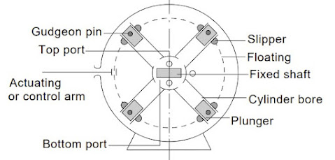
Radial piston pump:-
They are variable stroke pumps. A push rod (actuating or control arm) attached to the floating ring is capable to shift the floating ring left and right. Slippers in the track of floating ring upon which gudgeon pins are fitted, slippers are free to oscillate on gudgeon pins.
Pistons(7 or 9 in number) are connected to gudgeon pins and lies inside the cylinder block. The cylinder block is mounted on the shaft and rotate with it. Piston stroke changes with an eccentricity of the floating ring, it can change the direction as well as output quantity of the oil. At the time the centre of the rotating shaft and floating ring is the same the piston stroke is zero.
Axial piston pump:-
With the angular movement of the swash plate the direction of flow and rate of delivery is controlled. Ball ends of the Pistons fitted into a pocket in the wash plate. Cylinders housing the pistons are connected axially with the rotating shaft. The is no piston stroke when the swashplate is in a vertical position.
With the angular movement of the swash plate the direction of flow and rate of delivery is controlled. Ball ends of the Pistons fitted into a pocket in the wash plate. Cylinders housing the pistons are connected axially with the rotating shaft. The is no piston stroke when the swashplate is in a vertical position.

4. Oil Tanks:-
cast steel tanks containing hydraulic pumps along with linkage. pump control unit, servo pump unit & valve unit are mounted outside the tank. Oil filter, level gauge and drain plug etc. are also provided.
5. Oil block valve:-
The oil block valve blocks the oil return to the idle pump and so prevent it from reverse rotation. Also, this oil if not blocked it will not perform its duty of sliding rams. This valve is solenoid operated and in the de-energized condition, it keeps the returning oil block, while upon energizing the solenoid the valve will allow the oil to flow through.
The solenoid operation is delayed by few seconds to allow for the pump to start in unloaded condition. The OB valve is solenoid operated and thus angle limiter and power failure will de-energize the solenoid and left the valve in block position.
6. Continuous control system:-
The signal of the ordered rudder angle is compared with the feedback signal of the actual rudder angle at the steering stand and its deviation signal is transformed into the pump control signal in the control box. By this signal, the torque motor is driven and the hydraulic pump is tilted through the hydraulic regulator. The oil is consequently discharged from the hydraulic pump and applied to the hydraulic cylinder, and the tiller will be rotated through the ram and the ram pin.
The torque motor is stopped when the pump tilting angle reaches that corresponding to the pump control signal because the electric signal of the pump tilting angle is feed-backed to the control box by the differential transformer (LVDT) in the pump control unit. In proportion as the actual rudder angle nears to the order angle, the hydraulic pump returns to neutral position due to the reverse rotation of torque motor and the tiller stops when the actual rudder angle coincides with order angle and oil is not discharged from the hydraulic pump because the electric signal of actual rudder angle is feed-backed to the steering stand by the repeat back unit.
Components are as follows :
(1) Control Box
(2) Pump Control Unit
a. Hydraulic Regulator
b. Torque Motor
c. Differential Transformer LVDT
(3) Servo Pump Unit
(4) Relief Valve for Servo Pump
(5) Line filter
a. Indicator
b. Relief Valve
(6) Repeat Back Unit
(7) Rudder Angle Limiter
7. Steering gear:-
Rapson slide type:-it consists of the tiller, ram, ram pin & hydraulic cylinders.
The tiller is made of cast steel is fixed to the rudder stock with the key.
On the fork typed openings on the tiller, the hardened steel plates are bolted and they contact directly with the roller bearing of the ram. As the roller bearing rotates on this surface, the linear movement of the ram is converted to the circular motion of the tiller arm.
Ram & Hydraulic cylinder:-
The ram is made of carbon steel for machined structure and the hydraulic cylinder of nodular cast iron. The ram pin is incorporated into the centre of the ram having a surface finish and the rotary roller bearings are fitted into the upper and lower part of the ram pin. The ram thrust is transmitted to the tiller through the ram pin, therefore the material of high tensile strength is used.
Hydraulic cylinders are securely fitted on the bedplate of the hull. Inside the cylinder, a neck bushing is provided, which supports the ram. Five 'V' packings prevent oil leakage. The maximum angle for the rudder movement is 35 deg. A rudder angle limiter is provided at 36.6 deg and a mechanical stopper at 37 deg.
Modes of steering
Autopilot mode
At sea, steering is put on this mode of operation. Autopilot controls the steering gear system to turn the ship as per the set course. Autopilot receives an error signal from gyrocompass when the ship deviates from its course and sends a correcting signal to turn the rudder to maintain the correct course.

The operation gets cancelled when the desired angle is reached and the rudder returns to midship once the vessel is on course.
Follow-up mode
At restricted waters or low visibility manoeuvring, the steering is put on this mode. The helm order is given as required by the steering wheel, the moment of rudder stops when it reaches the desired angle.

The position of the rudder is fed back automatically through the hunting gear to the steering gear control.
Non-follow-up mode
When there is no feedback from the rudder due to a defective transmitter or hunting gear, the steering is put in this mode.
In this mode, the rudder continues to turn until the steering wheel returns to stop position and to turn the rudder back to midship the steering wheel needed to be move in the opposite direction.
Control system for steering gear
Operation:-
The signal of the ordered rudder angle is compared with the feedback signal of the actual rudder angle at the steering stand and its deviation signal is transformed into the pump control signal in the control box. By this signal, the torque motor is driven and the hydraulic pump is tilted through the hydraulic regulator. The oil is consequently discharged from the hydraulic pump and applied to the hydraulic cylinder, and the tiller will be rotated through the ram and the ram pin.
The torque motor is stopped when the pump tilting angle reaches that corresponding to the pump control signal because the electric signal of the pump tilting angle is feed-backed to the control box by the differential transformer (LVDT) in the pump control unit. In proportion, as the actual rudder angle nears the order angle, the hydraulic pump returns to neutral position due to the reverse rotation of torque motor and the tiller stops when the actual rudder angle coincides with the order angle and oil is not discharged from the hydraulic pump because the electric signal of actual rudder angle is feed-backed to the steering stand by the repeat back unit.
Construction :
(1) Control Box:
This box is to transform the deviation signal from the steering stand into the pump control signal and drive the torque motor. It also controls the solenoid control valve when the ruder angle limiter is operated.
(2) Pump Control Unit :
This unit consists of a hydraulic regulator, torque motor and pump tilting angle indicator plate, differential transformer (LVDT). The pump control signal from the control box drives the torque motor and the hydraulic pump is continuously controlled through the hydraulic regulator.
The differential transformer (LVDT) is also provided in order to feedback the electric signal of the pump tilting angle to the control box.
The pump control knob for local steering is usually mounted on the pump control unit and used when the autopilot system is failed or steering gear is adjusted.
(2.1) Hydraulic Regulator:
The pilot spool (202) of the hydraulic regulator is moved by the torque motor (101). The servo piston (403) connected to the cylinder casing of the hydraulic pump is also moved with the help of pressure oil generated from the servo pump and the oil is discharged from the hydraulic pump.
The operation of the regulator is explained by referring to Fig.
The rotor shaft of the torque motor is connected to the pilot spool (202) and rotational movement is converted to the stroke of the spool. The servo piston (403) is also connected to the tilting pin of the pump and the movement of the piston is transmitted to the pump. While the servo piston (403) is connected to the feed-back sleeve (203) through the feed-back lever (303) and the stroke of the piston is feed-backed to the feed-back sleeve.
When the pilot spool (202) is controlled to "pushing in" direction (rightward in the figure), pressure oil from servo pump is lead into chamber A (oil passage from a to b is closed).
The chamber B is opened to the drain through oil passage 'b' to 'c'. Accordingly, the servo piston (403) moves rightward and stops at the position where the feed-back sleeve (203) closes the oil passage 'b' to the drain, that is, the servo piston stops at the position corresponding to the stroke of the pilot spool (202).
Servo piston (403) tilts the pump in the same direction and by the same angle in accordance with the movement of the pilot spool (202). When the pilot spool (202) is controlled to "pulling out" direction (leftward in the figure), pressure oil is lead into both chambers 'A' and 'B'.
As the pressure receiving area of chamber 'B' is larger than that of 'A', the servo piston (403) moves leftward and stops at the position where the pilot spool stops.
At that position the oil passage from 'c' to the drain opens to chamber 'B' and the oil passage from 'a' to 'b' is closed.
Servo piston tilts the pump in the same direction and by the same angle in accordance with the movement of the pilot spool.
Also, the spring is provided in order to keep the pump at a neutral position (Tilting angle 0 degrees) when no force is given to the pilot spool. This spring returns the pilot spool to the neutral position when the control source of the torque motor is failed and the pump also returns to the neutral position.
Note: Neutral position has been adjusted and set the adjusting pin before delivery. Do not attempt to adjust the regulator at the field.
(2. 2) Torque Motor
A torque motor is provided in order to control the pilot spool and consists mainly of the frame, where the stator is mounted, the rotor with the spider and magnet fixed to the rotor shaft. The stopper with lever and bolt. The nameplate with pump tilting angle indicator etc. and installed on the casing of hydraulic regulator.
(2. 3) Differential Transformer LVDT.
LVDT is provided in order to detect the movement of the pilot spool and feedback the electric signal of the pump tilting angle to the control box. LVDT consists of the case with the coil, the spindle and core connected to the pilot spool of regulator etc. and is mounted on the casing of the regulator.
(3) Servo Pump Unit
Servo Pump Unit is provided in order to supply the pressure oil to the hydraulic regulator and OB valve and mounted on the oil tank. The servo pump is coupled to the electric motor through flexible coupling and started before the main pump/motor.
Servo Pump Unit is provided in order to supply the pressure oil to the hydraulic regulator and OB valve and mounted on the oil tank. The servo pump is coupled to the electric motor through flexible coupling and started before the main pump/motor.
(4) Relief Valve for Servo Pump
The relief valve is mounted on the manifold of the valve unit in order to adjust the servo pressure.
Adjusting pressure is 1. 8 - 2.0 MPa (18-20kgf/cm sq) and set before delivery.
(5) Line filter
The working oil flowed from the inlet of the filter by the servo pump is filtered while passing through the filter element from inside to outside and reaches the outlet, then actuates the hydraulic regulator and OB valve.
The filter consists of the cover with an indicator, the tee with a relief valve, the filter element, the drain plug, etc.
(5.1) Indicator During the filtration, the filtering surface is contaminated by the accumulated dirt in the oil and the differential pressure between the inlet and the outlet is increased, which causes a bad effect on the servo pump and hydraulic equipment. So the indicator is provided in order to know the degree of clogging condition (differential pressure) beforehand.
When the indicator ring (red) is floated up to the white level in the column (highest position). the differential pressure is 0.2 MPa{2kgf/cmsq}. In this case, the element must be cleaned.
However, it will be desirable to clean when the ring reaches the middle position in height (the differential pressure is 0.1 MPa (1kgf/cm sq) since after then the ring will reach the top position comparatively in a short time.
(5. 2) Relief Valve When the element is not cleaned although the indicator shows the clogging condition (highest position), the element may be damaged since the pressure on the element is increased due to the less allowable flow. The relief valve is provided in order to prevent the damage of hydraulic equipment and the valve is operated when the differential pressure is 0. 29-0.31 MPa (3.0~3.2kgf/cm sq) then a part of flow reaches the outlet directly without passing through the element.
(6) Repeat Back Unit
This unit is connected mechanically to the tiller in order to feed back the electric signal of the actual rudder angle to the steering stand.
(7) Rudder Angle Limiter
Rudder angle limiter is provided in order to stop the movement of steering gear instantaneously by canceling the electric signal to torque motor and de-energizing the solenoid valve consequently OB valve is unloaded when the steering gear will be moved by any reason over than the max. working angle (35 degrees on each side).
The limit switches are mounted between opposed hydraulic cylinders and operated by the movement of the ram.
Regulations for steering
SOLAS Chapter II-1: Construction – structure, stability, installations.
Regulation 29:- Steering gear
1. Unless expressly provided otherwise, every ship shall be provided with main steering gear and auxiliary steering gear to the satisfaction of the Administration. The main steering gear and the auxiliary steering gear shall be so arranged that the failure of one of them will not render the other one inoperative.2.1 All the steering gear components and the rudder stock shall be of sound and reliable construction to the satisfaction of the Administration. Special consideration shall be given to the suitability of any essential component which is not duplicated. Any such essential component shall, where appropriate, utilize antifriction bearings such as ball bearings, roller bearings or sleeve bearings which shall be permanently lubricated or provided with lubrication fittings.
the auxiliary steering gear;
the remote steering gear control systems;
the steering positions located on the navigation bridge;
the emergency power supply;
the rudder angle indicators in relation to the actual position of the rudder;
the remote steering gear control system power failure alarms;
the steering gear power unit failure alarms; and
2.2 The design pressure for calculations to determine the scantlings of piping and other steering gear components subjected to internal hydraulic pressure shall be at least 1.25 times the maximum working pressure to be expected under the operational conditions specified in paragraph 3.2, taking into account any pressure which may exist in the low-pressure side of the system. At the discretion of the Administration, fatigue criteria shall be applied for the design of piping and components, taking into account pulsating pressures due to dynamic loads.
2.3 Relief valves shall be fitted to any part of the hydraulic system which can be isolated and in which pressure can be generated from the power source or from external forces. The setting of the relief valves shall not exceed the design pressure. The valves shall be of adequate size and so arranged as to avoid an undue rise in pressure above the design pressure.
3 The main steering gear and rudder stock shall be:
of adequate strength and capable of steering the ship at maximum ahead service speed which shall be demonstrated; capable of putting the rudder over from 35 deg on one side to 35 deg on the other side with the ship at its deepest seagoing draught and running ahead at maximum ahead service speed and, under the same conditions, from 35 deg on either side to 30 deg on the other side in not more than 28 sec; operated by power where necessary to meet the requirements of paragraph 3.2 and in any case when the Administration requires a rudder stock of over 120 mm diameter in way of the tiller, excluding strengthening for navigation in ice; and so designed that they will not be damaged at maximum astern speed; however, this design requirement need not be proved by trials at maximum astern speed and maximum rudder angle.
of adequate strength and capable of steering the ship at maximum ahead service speed which shall be demonstrated; capable of putting the rudder over from 35 deg on one side to 35 deg on the other side with the ship at its deepest seagoing draught and running ahead at maximum ahead service speed and, under the same conditions, from 35 deg on either side to 30 deg on the other side in not more than 28 sec; operated by power where necessary to meet the requirements of paragraph 3.2 and in any case when the Administration requires a rudder stock of over 120 mm diameter in way of the tiller, excluding strengthening for navigation in ice; and so designed that they will not be damaged at maximum astern speed; however, this design requirement need not be proved by trials at maximum astern speed and maximum rudder angle.
4 The auxiliary steering gear shall be:
of adequate strength and capable of steering the ship at navigable speed and of being brought speedily into action in an emergency;
capable of putting the rudder over from 15 deg on one side to 15 deg on the other side in not more than 60 s with the ship at its deepest seagoing draught and running ahead at one half of the maximum ahead service speed or 7 knots, whichever is the greater; and
operated by power where necessary to meet the requirements of paragraph 4.2 and in any case when the Administration requires a rudder stock of over 230 mm diameter in way of the tiller, excluding strengthening for navigation in ice.
5 Main and auxiliary steering gear power units shall be:
arranged to restart automatically when power is restored after a power failure; and
arranged to restart automatically when power is restored after a power failure; and
capable of being brought into operation from a position on the navigation bridge. In the event of a power failure to any one of the steering gear power units, an audible and visual alarm shall be given on the navigation bridge.
6.1 Where the main steering gear comprises two or more identical power units, an auxiliary steering gear need not be fitted, provided that:
in a passenger ship, the main steering gear is capable of operating the rudder as required by paragraph 3.2 while any one of the power units is out of operation;
in a cargo ship, the main steering gear is capable of operating the rudder as required by paragraph 3.2 while operating with all power units;
the main steering gear is so arranged that after a single failure in its piping system or in one of the power units the defect can be isolated so that steering capability can be maintained or speedily regained.
6.2 The Administration may, until 1 September 1986, accept the fitting of a steering gear that has a proven record of reliability but does not comply with the requirements of paragraph 6.1.3 for a hydraulic system.
6.3 Steering gears, other than of the hydraulic type, shall achieve standards equivalent to the requirements of this paragraph to the satisfaction of the Administration.
7 Steering gear control shall be provided:
for the main steering gear, both on the navigation bridge and in the steering gear compartment;
where the main steering gear is arranged in accordance with paragraph 6, by two independent control systems, both operable from the navigation bridge. This does not require duplication of the steering wheel or steering lever. Where the control system consists of a hydraulic telemotor, a second independent system need not be fitted, except in a tanker, chemical tanker or gas carrier of 10,000 gross tonnages and upwards;
for the auxiliary steering gear, in the steering gear compartment and, if power-operated, it shall also be operable from the navigation bridge and shall be independent of the control system for the main steering gear.
8 Any main and auxiliary steering gear control system operable from the navigation bridge shall comply with the following:
if electric, it shall be served by its own separate circuit supplied from a steering gear power circuit from a point within the steering gear compartment, or directly from switchboard busbars supplying that steering gear power circuit at a point on the switchboard adjacent to the supply to the steering gear power circuit;
means shall be provided in the steering gear compartment for disconnecting any control system operable from the navigation bridge from the steering gear it serves;
the system shall be capable of being brought into operation from a position on the navigation bridge; in the event of a failure of electrical power supply to the control system, an audible and visual alarm shall be given on the navigation bridge; and
short circuit protection only shall be provided for steering gear control supply circuits.
9 The electrical power circuits and the steering gear control systems with their associated components, cables and pipes required by this regulation and by regulation 30 shall be separated as far as is practicable throughout their length.
10 A means of communication shall be provided between the navigation bridge and the steering gear compartment.
11 The angular position of the rudder shall:
if the main steering gear is power-operated, be indicated on the navigation bridge. The rudder angle indication shall be independent of the steering gear control system;
be recognizable in the steering gear compartment.
if the main steering gear is power-operated, be indicated on the navigation bridge. The rudder angle indication shall be independent of the steering gear control system;
be recognizable in the steering gear compartment.
12 Hydraulic power-operated steering gear shall be provided with the following:
arrangements to maintain the cleanliness of the hydraulic fluid taking into consideration the type and design of the hydraulic system;
a low-level alarm for each hydraulic fluid reservoir to give the earliest practicable indication of hydraulic fluid leakage. Audible and visual alarms shall be given on the navigation bridge and in the machinery space where they can be readily observed; and a fixed storage tank having sufficient capacity to recharge at least one power actuating system including the reservoir, where the main steering gear is required to be power-operated. The storage tank shall be permanently connected by piping in such a manner that the hydraulic systems can be readily recharged from a position within the steering gear compartment and shall be provided with a contents gauge.
13 The steering gear compartments shall be:
readily accessible and, as far as practicable, separated from machinery spaces; and
provided with suitable arrangements to ensure working access to steering gear machinery and controls. These arrangements shall include handrails and gratings or other nonslip surfaces to ensure suitable working conditions in the event of hydraulic fluid leakage.
14 Where the rudder stock is required to be over 230 mm diameter in way of the tiller, excluding strengthening for navigation in ice, an alternative power supply, sufficient at least to supply the steering gear power unit which complies with the requirements of paragraph 4.2 and also its associated control system and the rudder angle indicator, shall be provided automatically, within 45 sec, either from the emergency source of electrical power or from an independent source of power located in the steering gear compartment. This independent source of power shall be used only for this purpose. In every ship of 10,000 gross tonnages and upwards, the alternative power supply shall have a capacity for at least 30 min of continuous operation and in any other ship for at least 10 min.
15 In every tanker, chemical tanker or gas carrier of 10,000 gross tonnages and upwards and in every other ship of 70,000 gross tonnages and upwards, the main steering gear shall comprise two or more identical power units complying with the provisions of paragraph 6.
16 Every tanker, chemical tanker or gas carrier of 10,000 gross tonnages and upwards shall, subject to paragraph 17, comply with the following:
the main steering gear shall be so arranged that in the event of loss of steering capability due to a single failure in any part of one of the power actuating systems of the main steering gear, excluding the tiller, quadrant or components serving the same purpose, or seizure of the rudder actuators, steering capability shall be regained in not more than 45 sec after the loss of one power actuating system;
the main steering gear shall comprise either:
two independent and separate power actuating systems, each capable of meeting the requirements of paragraph 3.2; or at least two identical power actuating systems which, acting simultaneously in normal operation, shall be capable of meeting the requirements of paragraph 3.2. Where necessary to comply with this requirement, interconnection of hydraulic power actuating systems shall be provided. Loss of hydraulic fluid from one system shall be capable of being detected and the defective system automatically isolated so that the other actuating system or systems shall remain fully operational;
steering gears other than of the hydraulic type shall achieve equivalent standards.
17 For tankers, chemical tankers or gas carriers of 10,000 gross tonnages and upwards, but of less than 100,000 tonnes deadweight, solutions other than those set out in paragraph 16, which need not apply the single failure criterion to the rudder actuator or actuators, may be permitted provided that an equivalent safety standard is achieved and that:
following the loss of steering capability due to a single failure of any part of the piping system or in one of the power units, steering capability shall be regained within 45 s; and
where the steering gear includes only a single rudder actuator, special consideration is given to stress analysis for the design including fatigue analysis and fracture mechanics analysis, as appropriate, to the material used, to the installation of sealing arrangements and to testing and inspection and to the provision of effective maintenance. In consideration of the foregoing, the Administration shall adopt regulations which include the provisions of the Guidelines for acceptance of non-duplicated rudder actuators for tankers, chemical tankers and gas carriers of 10,000 gross tonnages and above but less than 100,000 tonnes deadweight, adopted by the Organization.
18 For a tanker, chemical tanker or gas carrier of 10,000 gross tonnages and upwards, but less than 70,000 tonnes deadweight, the Administration may, until 1 September 1986, accept a steering gear system with a proven record of reliability which does not comply with the single failure criterion required for a hydraulic system in paragraph 16.
19 Every tanker, chemical tanker or gas carrier of 10,000 gross tonnages and upwards, constructed before 1 September 1984, shall comply, not later than 1 September 1986, with the following:
the requirements of paragraphs 7.1, 8.2, 8.4, 10, 11, 12.2, 12.3 and 13.2;
two independent steering gear control systems shall be provided each of which can be operated from the navigation bridge. This does not require duplication of the steering wheel or steering lever;
if the steering gear control system in operation fails, the second system shall be capable of being brought into immediate operation from the navigation bridge; and
each steering gear control system, if electric, shall be served by its own separate circuit supplied from the steering gear power circuit or directly from switchboard busbars supplying that steering gear power circuit at a point on the switchboard adjacent to the supply to the steering gear power circuit.
20 In addition to the requirements of paragraph 19, in every tanker, chemical tanker or gas carrier of 40,000 gross tonnages and upwards, constructed before 1 September 1984, the steering gear shall, not later than 1 September 1988, be so arranged that, in the event of a single failure of the piping or of one of the power units, steering capability can be maintained or the rudder movement can be limited so that steering capability can be speedily regained. This shall be achieved by:
an independent means of restraining the rudder; or
fast-acting valves which may be manually operated to isolate the actuator or actuators from the external hydraulic piping together with a means of directly refilling the actuators by a fixed independent power-operated pump and piping system; or
an arrangement such that, where hydraulic power systems are interconnected, loss of hydraulic fluid from one system shall be detected and the defective system isolated either automatically or from the navigation bridge so that the other system remains fully operational.
Regulation 30:-
Additional requirements for electric and electro-hydraulic steering gear
1 Means for indicating that the motors of the electric and electro-hydraulic steering gear are running shall be installed on the navigation bridge and at a suitable main machinery control position.
2 Each electric or electrohydraulic steering gear comprising one or more power units shall be served by at least two exclusive circuits fed directly from the main switchboard; however, one of the circuits may be supplied through the emergency switchboard. An auxiliary electric or electrohydraulic steering gear associated with a main electric or electrohydraulic steering gear may be connected to one of the circuits supplying this main steering gear. The circuits supplying an electric or electrohydraulic steering gear shall have an adequate rating for supplying all motors which can be simultaneously connected to them and may be required to operate simultaneously.
3 Short circuit protection and an overload alarm shall be provided for such circuits and motors. Protection against excess current, including starting current, if provided, shall be for not less than twice the full load current of the motor or circuit so protected, and shall be arranged to permit the passage of the appropriate starting currents. Where a three-phase supply is used an alarm shall be provided that will indicate failure of any one of the supply phases. The alarms required in this paragraph shall be both audible and visual and shall be situated in a conspicuous position in the main machinery space or control room from which the main machinery is normally controlled and as may be required by regulation 51.
4 When in a ship of less than 1,600 gross tonnages, An auxiliary steering gear which is required by regulation 29.4.3 to be operated by power is not electrically powered or is powered by an electric motor primarily intended for other services, the main steering gear may be fed by one circuit from the main switchboard. Where such an electric motor primarily intended for other services is arranged to power such an auxiliary steering gear, the requirement of paragraph 3 may be waived by the Administration if satisfied with the protection arrangement together with the requirements of regulation 29.5.1 and .2 and 29.7.3 applicable to the auxiliary steering gear.
SOLAS Chapter V: Safety of navigation
Regulation 26:- Steering gear: testing and drills
1. Within 12 hours before departure, the ship’s steering gear shall be checked and tested by the ship’s crew. The test procedure shall include, where applicable, the operation of the following:
the main steering gear;Regulation 26:- Steering gear: testing and drills
1. Within 12 hours before departure, the ship’s steering gear shall be checked and tested by the ship’s crew. The test procedure shall include, where applicable, the operation of the following:
the auxiliary steering gear;
the remote steering gear control systems;
the steering positions located on the navigation bridge;
the emergency power supply;
the rudder angle indicators in relation to the actual position of the rudder;
the remote steering gear control system power failure alarms;
the steering gear power unit failure alarms; and
automatic isolating arrangements and other automatic equipment.
2. The checks and tests shall include:
the full movement of the rudder according to the required capabilities of the steering gear;
a visual inspection of the steering gear and its connecting linkage; and
the operation of the means of communication between the navigation bridge and steering gear compartment.
3.1 Simple operating instructions with a block diagram showing the change-over procedures for remote steering gear control systems and steering gear power units shall be permanently displayed on the navigation bridge and in the steering compartment.the full movement of the rudder according to the required capabilities of the steering gear;
a visual inspection of the steering gear and its connecting linkage; and
the operation of the means of communication between the navigation bridge and steering gear compartment.
3.2 All ships’ officers concerned with the operation and/or maintenance of steering gear shall be familiar with the operation of the steering systems fitted on the ship and with the procedures for changing from one system to another.
4. In addition to the routine checks and tests prescribed in paragraphs 1 and 2, emergency steering drills shall take place at least once every three months in order to practise emergency steering procedures. These drills shall include direct control within the steering gear compartment, the communications procedure with the navigation bridge and, where applicable, the operation of alternative power supplies.
5. The Administration may waive the requirements to carry out the checks and tests prescribed in paragraphs 1 and 2 for ships that regularly engage on voyages of short duration. Such ships shall carry out these checks and tests at least once every week.
6. The date upon which the checks and tests prescribed in paragraphs 1 and 2 are carried out and the date and details of emergency steering drills carried out under paragraph 4 shall be recorded.
thank you sir... its really helpful for my exam
ReplyDelete