
Naval Architecture
Intact stability criteria
Drydocking and Grounding
Wake
Thrust
Relation between Powers
Cavitation
G. Rudder Theory
Thrust
Relation between Powers
Cavitation
G. Rudder Theory
Forces on rudder
Torque on stock
Centre of rotation or pivot point
Torque on stock
Centre of rotation or pivot point
The angle of the heel while turning
Function: Controlling the Operation of The Ship & Care for Persons on Board at Management Level

Naval Architecture
Title A: Pressure and Load exerted by the liquid
1. Density, $\displaystyle \small \mathrm{\rho =\frac{Mass}{Volume}\ \ tonne/m^3}$
2. Relative density $\displaystyle \small \mathrm{rd=\frac{Density\ of\ Substance}{Density\ of\ Freshwater}}$
3. Pressure at the base of container = ρgh $\displaystyle \small \mathrm{kN/m^{2}}$
where; g= acceleration due to gravity ($\displaystyle \small \mathrm{m/s^{2}}$ ).
h= height of liquid(m).
4. Total load on a horizontal plane exerted by liquid $\displaystyle \small \mathrm{= \rho gh\times A\ \ kN}$
5. Total load on an Inclined plane exerted by liquid $\displaystyle \small \mathrm{= \rho gH\times A\ \ kN}$
Where; H = distance of centroid of the plane from the liquid surface.
for a vertical bulkhead $\displaystyle \small \mathrm{H = \frac{h}{2}}$ .
6. Centre of pressure on an immersed plane is the point at which the whole liquid may be regarded as acting.
Centre of pressure from surface = $\displaystyle \small \mathrm{\frac{2^{nd}\ moment\ of\ area\ about\ surface\left ( I_{OO} \right )}{1^{st}\ moment\ of\ area\ about\ surface\ (A\times H)}}$ .
$\displaystyle \small \mathrm{I_{NA}}$ = 2nd moment about an axis through centroid or neutral axis.
$\displaystyle \small \mathrm{I_{oo}}$ = 2nd moment about an O-O parallel to neutral axis at a distance H from it is given by:
$\displaystyle \small \mathrm{I_{oo}}$ = $\displaystyle \small \mathrm{(I_{NA}) + AH^{2}}$
Thus, centre of pressure from surface $\displaystyle \small \mathrm{= \frac{I_{NA}}{A.H}+H}$
{$\displaystyle \small \mathrm{I_{NA}}$ for rectangle, triangle and circle are $\displaystyle \small \mathrm{\small \frac{1}{12}BD^{3}, \frac{1}{36}BD^{3} and \frac{\pi}{64}D^{4}}$ respectively }
{ Centre of pressure from O-O for rectangle, triangle and circle are $\displaystyle \small \mathrm{\frac{2D}{3}}$ , $\displaystyle \small \mathrm{\frac{D}{2}}$ and $\displaystyle \small \mathrm{\frac{5D}{8}}$ respectively.}
7. Load diagram is drawn with the height of the liquid on the y-axis and the load per meter on the x-axis.
Load per meter at various heights can be calculated by multiplication of pressure at that point with the width of the plane at that point (ρgh x w).
The area of this diagram represents the load on the plane, while its centroid represents the position of the centre of pressure.
When the top edge of the plane is at the liquid surface the pressure at that edge is zero and hence load per meter is also zero.
A rectangular plane has a constant width thus forms a right-Triangle load diagram. While for a triangular plane, the load diagram is parabolic.
8. Shearing force on bulkhead stiffeners: at top = $\displaystyle \small \mathrm{\frac{1P}{3}}$ , at bottom =$\displaystyle \small \mathrm{\frac{-2P}{3}}$ and zero at $\displaystyle \small \mathrm{L/\sqrt{3}}$ from top. Where P is the load on stiffeners.
Title B: Displacement TPC and Coeff. of forms
1. Archimedes Principle:- If a solid body is immersed in a liquid, there is an apparent loss in weight. This loss is equal to the upthrust exerted by the liquid on the body. The upthrust is equal to the weight of the volume of liquid displaced by the body.
2. Displacement:- When a ship is floating freely at rest the mass of the ship is equal to the mass of the volume of water displaced by the ship and is therefore known as displacement of the ship.
Δ(Displacement in tonne) = ρ(Density of liquid) x ▽(Displacement in cubic-meter).
Mass of ship = Δ tonne
Weight of ship = Δ.g kN
3. Centre of Buoyancy:-
Buoyancy is the upthrust exerted by the liquid. The force of buoyancy act at the centre of buoyancy, which is the centre of gravity of the underwater volume of the ship.
LCB (longitudinal position of the centre of buoyancy), is the distance of the Centre of buoyancy aft or fwd from midship.
VCB (vertical position of the centre of buoyancy), is the distance of the centre of buoyancy measured above the keel. Denoted by KB.
VCB can be calculated
(a) from the displacement curve,

VCB below water line
= area between displacement curve and draught axis/displacement
= $\displaystyle \small \mathrm{\frac{a}{\Delta }}$
(b) by morrishes approximate formula
VCB below water line $\displaystyle \small \mathrm{=\frac{1}{3}\left ( \frac{d}{2}+\frac{\bigtriangledown }{A_{w}} \right )}$
Where, d= draught in meter
▽ = volume of displacement in cubic meter.
Aw = water plane area in $\displaystyle \small \mathrm{m^{2}}$.
4. TPC (tonne per centimetre immersion): TPC of a ship at any given draught is the mass required to change the draught by one centimetre.
$\displaystyle \small \mathrm{TPC = A_w\times \frac{\rho }{100}}$ .
Aw = water plane area in $\displaystyle \small \mathrm{m^{2}}$.
For seawater, $\displaystyle \small \mathrm{\rho =1.025\ t/m^{3}}$
Increase in draught $\displaystyle \small \mathrm{TPC = \frac{Mass\ added }{TPC}}$ .
5. Coefficients of form:
Coefficients of form have been devised to show the relationship between the form of the ship and the dimensions of the ship.
Water plane area coefficient $\displaystyle \small \mathrm{(C_w)=\frac{A_w}{LB}}$ .
Midship section area coefficient $\displaystyle \small \mathrm{(C_m)=\frac{A_m}{Bd}}$
Block coefficient or coefficient of fitness $\displaystyle \small \mathrm{(C_b)=\frac{\bigtriangledown }{LBd}}$ .
Prismatic coefficient $\displaystyle \small \mathrm{(C_p)=\frac{\bigtriangledown }{LA_m}}$ .
Thus,
$\displaystyle \small \mathrm{C_p=\frac{C_b}{C_m}}$ .- The Waterplane area coefficient expresses the fullness of the waterplane or the ratio of the waterplane area to a rectangle of the same length and width. A low waterplane coefficient figure indicates fine ends and a high waterplane coefficient indicates fuller ends. A high coefficient of water plane value improves stability as well as handling behaviour in rough conditions.
- The prismatic coefficient is used to evaluate the distribution of the volume of the underwater body. A low or fine prismatic coefficient indicates a full mid-section and fine ends, a high or full prismatic coefficient indicates a boat with fuller ends.
- Block coefficient gives a sense of how much of the block is defined by the length, & the draft is filled by the hull. Full forms such as oil tankers will have a high block coefficient whereas fine shapes such as sailboats will have a low coefficient.
- The midship coefficient defines the fullness of the underwater body. A low value of midship coefficient indicates a cut-away mid-section and a high value indicates a boxy section shape. Sailboats have a cut-away mid-section with a low midship coefficient whereas cargo vessels have a boxy section with a high midship coefficient.
6. Wetted surface area:- The area of ship's hull in contact with water can be approximately calculated by:
Denny’s formula, $\displaystyle \small \mathrm{S=1.7Ld +\frac{\bigtriangledown }{d}}$
Taylor's formula, $\displaystyle \small \mathrm{S=c\sqrt{\Delta.L}}$
Where
Where
S= wetted surface area in $\displaystyle \small \mathrm{m^{2}}$.
L= Length of the ship in meter
d= draught in m
⛛ =volume in $\displaystyle \small \mathrm{m^{3}}$.
Δ = displacement in tonne
c = a coefficient of about 2.6 which depends upon the shape of the ship.
7. Similar figures
If, L = length of the ship
S = wetted surface area
△ = Displacement
Then,
$\displaystyle \small \mathrm{\small S\ \alpha\ L^{2}}$ and $\displaystyle \small \mathrm{\small \Delta\ \alpha\ L^{3}}$
Thus,$\displaystyle \small \mathrm{\small \Delta\ \alpha\ S^{3/2}}$
Hydrostatic curves
A series of graphs are drawn to a vertical scale of draught and a base of length, which gives values such as the center of buoyancy, displacement, moment causing unit trim, and center of flotation. In practice tables with hydrostatic parameters calculated for different draughts are used. However, only by having traditional graphs, it is possible to observe the character of hydrostatic curves and understand ship behavior... Read a detailed article.
 |
| Hydrostatic curves |
Bonjean Curves
- The curves of areas of transverse sections and their moments about the baseline of a ship are used in making calculations (example: to determine the force of buoyancy during launching).
- It can also be defined as a curve formed by plotting transverse sectional areas measured up to each waterline against a vertical axis representing the waterline; thus the horizontal distance measured from the curve to the vertical axis gives the area of the section from the baseline to that particular waterline; usually sets of curves are obtained for each section; these curves facilitate immersed volume to be obtained for the water lines that are not parallel to baseline.
- The curves of the cross-sectional area for all stations are collectively called Bonjean Curves.
 |
| Bonjean curve |
- The diagram shows a set of fair curves formed by plotting the areas of transverse sections up to successive waterlines. At each station along the length of the ship, a curve of the transverse shape of the hull is drawn.
- The areas of these transverse sections up to each successive waterline are calculated, and the value is plotted on a graph. By convention, the Bonjean curves are superimposed onto the ship's profile.
- Any predicted waterline required can be drawn on the completed Bonjean curve/profile. One of the principal uses; to determine volume displacement of the ship and its LCB at any draught level, at any trimmed condition.
- A standard method used is by integrating transverse areas.
- If the water lines are in trim condition, the Bonjean Curves are particularly useful.
- In the case of a trimmed waterline, the trim line may be drawn on the profile of the ship. Then, drafts are read at which the Bonjean Curve are to be entered.
- By drawing a straight line across the contracted profile, the drafts at which the curves are to be read appear directly at each station.
- From there, the values of sectional areas are taken individually at the intersection of the line of drafts drawn and area curves.
- All the obtained sectional area values then can be integrated (eg. Simpson Method) in order to determine the volume of displacement.
Angle of repose
When a ship carries dry bulk cargo such as grain, ore & coal. Bulk cargoes settle down when the ship goes to sea so that holds which were full initially, have void space at the top. All materials of this type have an angle of repose.
If the ship rolls to a greater angle than this they may move to one side and not move back later. Consequently, there can be a permanent transfer of weight to one side resulting in a permanent list, with a reduction of stability on that side. This shifting of cargo on one side causes shifting of the centre of gravity or G moves.
To preventing shifting of cargo:-
(i) Use of shifting boards.
(ii) Centreline Bulkhead.
(iii) Loading (By trimming the ship to fill all the spaces between beams and at the ends and side of hold).
Centre of Gravity
Centre of Gravity: It is an imaginary point where the whole weight of the body is assumed to be concentrated.
The vertical position of the centre of gravity (VCG) of the ship above the keel and this distance is denoted by KG.
The height of the centre of gravity, $\displaystyle \small \mathrm{KG = \frac{total\ moment}{total\ diaplacement}}$
where the total moment is the sum of the moment of individual masses on the ship
The moment of individual masses can be calculated by multiplying masses to their distance above the keel.
The longitudinal position of the centre of gravity (LCG) is given as a distance forward or aft of midships.
Addition of mass on a ship: This will cause the centre of gravity to shift depending on the location of the mass added.
If the mass is added forward of the midship then there will be an excess moment forward.
This aexcess moment is the difference of moment caused by the mass added and moment of original LCG (considering the signs).
Longitudinal position of centre of gravity will then be calculated by dividing this excess moment by total displacement.
Similarly new KG can be find by dividing the sum of moments of masses from keel by the total displacement.
Movement of mass on a ship will cause the centre of gravity to shift. This can be calculated as,
$\displaystyle \small \mathrm{Shift\ in\ centre\ of\ Gravity = \frac{mass\ moved\times distance\ moved}{total\ mass}}$
When a mass is suspended by a crane that means it is clear of the deck, its COG will be raised to the derrick head.
Title C: Simpson's Rule.
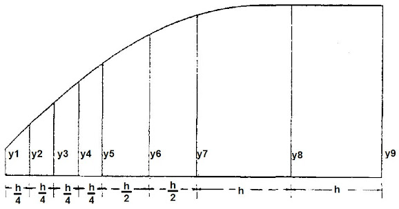
Simpson's first rule is based on the assumption that the curved portion of a figure forms part of a parabola and gives the area contained between three consecutive, equally-spaced ordinates.
This rule may be applied repeatedly to determine the area of a larger plane.
The following figures will illustrate the use of Simpson's rule:
Case 1: $\displaystyle \small \mathrm{Area\ ABCD = \frac{h}{3}(1y_{1}+4y_{2}+1y_{3})}$

Case 2:$\displaystyle \small \mathrm{Area\ PQRS = \frac{h}{3}(1y_{1}+4y_{2}+2y_{3}+4y_{4}+2y_{5}+4y_{6}+1y_{7})}$
 |
Case 3: $\displaystyle \small \mathrm{Area\ = \frac{h}{4\times 3}(1y_{1}+4y_{2}+2y_{3}+4y_{4}+1y_{5})}+ \frac{h}{2\times 3}(1y_{5}+4y_{6}+1y_{7})+\frac{h}{3}(1y_{7}+4y_{8}+1y_{9})$
$\displaystyle \small \mathrm{Area\ = \frac{h}{3}(\frac{1}{4}y_{1}+1y_{2}+\frac{1}{2}y_{3}+1y_{4}+\frac{3}{4}y_{5}+2y_{6}+\frac{3}{2}y_{7}+4y_{8}+1y_{9})}$
Title D: Stability.
Various information from Statical Stability curve
Range of Stability;
The angle of vanishing stability;
Maximum GZ;
Initial GM;
Point of inflexion or contra-flexure;
Angle of loll;
Statical stability
It is the measure of the tendency of a ship to return to the upright if inclined by an external force.
If the vessel is stated to be upright, it should be regarded as rolling slightly about the upright position.
In the upright position, the weight of the ship acts vertically down through the centre of gravity G, while upthrust acts through the centre of buoyancy B.
Since the weight is equal to the upthrust, and the centre of gravity and centre of buoyancy is in the same verticle line, the ship is in equilibrium.
When the ship is inclined by an external force to an angle θ, the centre of gravity remains in the same position but the centre of buoyancy shifts from B to  . This creates a moment that tends to return the ship upright, called rightening moment and is equals to Δg x GZ, where GZ is called a rightening lever. Since the moment tends to upright the ship, the ship is said to be stable.

The verticle line through is intersecting the centre line at M (Transverse metacentre). From figure above GZ=GMsinθ., for small angles of heel upto 10°. GM is known as metacentric height.
a) Positive GM:- G lies below M.
b) Negative GM:- M lies below G. GZ acts in oppostie direction and the anlge of heel will keep on increasing. vessel is said to be Unstable and will not return upright.
c) Neutal equillibrium:- When G & M coincide, there is no moment acting on the ship, which will therefore remain inclined to an angle θ.

Tender ship:- A ship with small GM will have small GZ and roll easily. Have long rolling period and comfortable.
Stiff ship:- Having large GM will have large GZ and considerable resistance to rolling. Have small rolling period and is Uncomfotable. May result in structural damage.
How to find position of M?
The distance of the transverse distance of M above keel, i.e KM is given by,$\displaystyle \small \mathrm{KM = KB +BM}$,
How to find position of M?
The distance of the transverse distance of M above keel, i.e KM is given by,$\displaystyle \small \mathrm{KM = KB +BM}$,
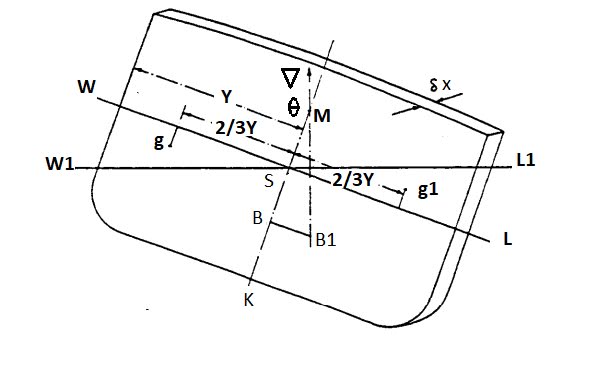
from figure;$\displaystyle \small \mathrm{BB_1= BMtan\theta }$
thus, $\displaystyle \mathrm{BM= \frac{BB_1}{tan\theta}}$
Now from figure we can see
$\displaystyle \small \mathrm{\frac{BB1}{gg1}=\frac{V}{\bigtriangledown}}$
Where, V = volume of the wedge and gg1 = transverse shift in centre of gravity of wedge.
thus, $\displaystyle \small \mathrm{BM=\frac{V\times gg1}{\bigtriangledown\times tan\theta }}$
Now to determine V x gg1:
For small angles, say 2 or 3 degrees, the upright and inclined waterlines will intersect at O on the centreline. The volumes of the emerged and immersed wedges must be equal for constant displacement. For small angles the emerged and immersed wedges at any section, are approximately triangular. If y is the half ordinate of the original waterline at the cross-section the emerged or immersed section area is:$\displaystyle \small \mathrm{\frac{1}{2}y \times ytan\theta =\frac{1}{2}y^{2}tan\theta}$
For small angles, say 2 or 3 degrees, the upright and inclined waterlines will intersect at O on the centreline. The volumes of the emerged and immersed wedges must be equal for constant displacement. For small angles the emerged and immersed wedges at any section, are approximately triangular. If y is the half ordinate of the original waterline at the cross-section the emerged or immersed section area is:$\displaystyle \small \mathrm{\frac{1}{2}y \times ytan\theta =\frac{1}{2}y^{2}tan\theta}$
for small angles, and the total volume of each wedge is:$\displaystyle \small \mathrm{\int \frac{1}{2}y^{2}\theta.dx}$
integrated along the length of the ship.
This volume is effectively moved from one side to the other and for triangular sections the transverse movement will be 4y/3 giving a total transverse shift of buoyancy of:
This volume is effectively moved from one side to the other and for triangular sections the transverse movement will be 4y/3 giving a total transverse shift of buoyancy of:
$\displaystyle \small \mathrm{\int \frac{1}{2}y^{2}\theta.dx\ \times \frac{4}{3}y=\theta \int \frac{2}{3}y^{3}.dx}$
since θ is constant along the length of the ship.
The expression within the integral sign is the second moment of area, or the moment of inertia, of a waterplane about its centreline. It may be denoted by Ⅰ, whence the transverse movement of buoyancy is:Ⅰθ
thus we can say the total moment of the shift of wedge is:Ⅰθ
Now from, $\displaystyle \small \mathrm{BM=\frac{V x gg1}{\bigtriangledown x tan\theta }}$
tanθ≈θ , thus the equation will become $\displaystyle \small \mathrm{BM=\frac{V\times gg1}{\bigtriangledown\times \theta }}$
V x gg1 can be replaced by Iθ
Thus $\displaystyle \small \mathrm{BM=\frac{I\times \theta }{\bigtriangledown\times \theta }}$
or $\displaystyle \small \mathrm{BM=\frac{I }{\bigtriangledown }}$
This expression can be used to find KM of ships with different geometry.$\displaystyle \small \mathrm{KM = KB +BM}$.
(1) for a box shape ship
$\displaystyle \small \mathrm{KB = \frac{d}{2}}$
$\displaystyle \small \mathrm{I=\frac{1}{12}LB^{3}}$
$\displaystyle \small \mathrm{\bigtriangledown = L.B.d}$
thus, $\displaystyle \small \mathrm{KM =\frac{d}{2}+\frac{B^{2}}{12d}}$
(2) for a constant triangular shape
$\displaystyle \small \mathrm{KB = \frac{2d}{3}}$
$\displaystyle \small \mathrm{I=\frac{1}{12}Lb^{3}}$
this value is still same because the hull on ship side whose second moment it is of rectangular shape."b" here is the breadth at the water line.
b is first needed to be find in relation to B.
b is first needed to be find in relation to B.
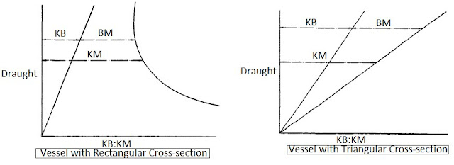
Metacentric Diagram
KB and BM depends on draught, there valves for any ship may be calculated for a number of different draughts.

Inclining experiment
This experiment is carried out on completed ship to determine the metacentric height, hence the hight of centre of gravity. by knowing the height of centre of gravity of light ship, the hight of centre of gravity of ship at any loaded condition can be determined. This is therefore necessary to carry out the experiment on the empty ship as far as possible. This ship should be in sheltered position and the weather should be calm. Only the person required for the experiment to carry out should be allowed onboard. All tanks should be emptied or pressed up tight. Magnitude and position of all the masses which are not included in the light weight ship should be noted and corrections are made.
 If △ = displacement of the ship
Then, $\displaystyle \small \mathrm{GG1 = m\times \frac{d}{\Delta }}$
From figure, $\displaystyle \small \mathrm{GG1 = GM\times tan\theta }$
$\displaystyle \small \mathrm{GM\ tan\theta = m\times\frac{d}{\Delta }}$
$\displaystyle \small \mathrm{GM = \frac{m\times d}{\Delta\ tan\theta }}$
Thus if, l = length
$\displaystyle \small \mathrm{tan\theta =\frac{a}{l}}$
$\displaystyle \small \mathrm{GM = \frac{m\times d\times l}{\Delta \times a}}$
$\displaystyle \small \mathrm{KG = KM - GM}$
If △ = displacement of the ship
Then, $\displaystyle \small \mathrm{GG1 = m\times \frac{d}{\Delta }}$
From figure, $\displaystyle \small \mathrm{GG1 = GM\times tan\theta }$
$\displaystyle \small \mathrm{GM\ tan\theta = m\times\frac{d}{\Delta }}$
$\displaystyle \small \mathrm{GM = \frac{m\times d}{\Delta\ tan\theta }}$
Thus if, l = length
$\displaystyle \small \mathrm{tan\theta =\frac{a}{l}}$
$\displaystyle \small \mathrm{GM = \frac{m\times d\times l}{\Delta \times a}}$
$\displaystyle \small \mathrm{KG = KM - GM}$

The experiment should be commenced with the ship upright. Four masses are placed on the deck, two on each side of ship near midship, their centres must be as far as possible. Mooring ropes are slackened, gangway removed, density of water and draught noted accuratly.
Atleast two pandulums are used one forward and one aft. they are made as long as possible and are suspended from some convenient point. A stool is arranged in a way of each pandulum on which the deflections are recorded. the pandulum bobs are immursed in water or light oil to dampen the swing.
The masses are then moved one at a time, across the ship utill all four are on one side, then all four on other side, then on other side and finally two on each side. The deflection of pandulums are recorded for each movement of mass. An average of these deflection is used to determine the metacentric height.

Stabilograph is an instrument used by shipyards to record the inclinations, it consists of a heavy metal pendulum balanced on knife edge, geared to a pen arm, which records the angle of heel on a rotating drum. Advantages of the stabilograph are that a permanent record is obtained and the movement of the ship may be seen as the experiment is in progress. Any restriction on heeling will cause the irregular movement will be seen on the drum.
Free surface effect
When a tank is partially filled, the liquid’s centre of gravity position will change as the ship is inclined. Liquid in partially filled tank always decreases the initial metacentric height GM, righting lever GZ, and angle of vanishing stability.
A partially filled tank is know as a “slack tank”. The reduction of stability caused by the liquids in slack tanks is known as free-surface effect. This adverse effect on the stability is referred to as a “loss in GM” or as a “virtual rise in vertical centre of gravity KG” and is calculated as follows:
Loss in GM due to free surface effects (in metres) = Free surface moment (tones metres) x Specific gravity of liquid in tank/Displacement of vessel in tonnes
The free-surface effect can endanger the ship or even lead to a negative metacentric height. Therefore the number of partially filled tanks should be kept to a minimum. When ballasting the vessel, only one transverse pair or a single centerline ballast tank should be filled up. At sea, as far as possible, ballast tanks shall be 100% full or empty. When ballasted, wide double bottom tanks must be always 100% full.Stability at large angle of heel (cross-curves)
- When the heel angle is greater than 10 °. Then the principles on which initial stability were based are no longer true. Assumptions were made that the two water planes intersect at centre line and the wedges are right angled triangles. Those assumptions can not be made for a large angle of heel and the stability of the ship is determined from first principle.

- Since the actual position of G is not known, thus it is assumed at some convenient position above keel. Sections through the ship are drawn at intervals along the ships length. These sections are inclined to an angle say 15°.
- The integrator is set with its axis in the verticle through G. The outline of each section is traced by integrator upto a given water line and the displacement and rightening lever obtained. This is repeated for different waterlines and for angles of 30°, 45°, 60°, 70° & 90°.
- The GZ values at each angle are plotted on the base of displacement to form the cross curves of the stability for the ship.
- The displacement, height of centre of gravity and metacentric height of a ship may be calculated for any loaded consition. At this displacement the rightening lever may by obtain at respective angles for the assumed position of the centre of gravity. These values may be amended to suit the actual height of centre of gravity.

- let G = assumed position of COG.
G1 = actual poition of COG.
if G1 lies below G, then the ship is more stable and G1Z=GZ + GG1sinθ.
if G1 lies above G, then the ship is less stable and G1Z=GZ - GG1sinθ.
- The amended rightening levers are plotted on a base of angle of heel to form the curve of statical stability for the ship in this condition of loading. The initial slope of the curve lies along the line drawn from the origin to GM plotted vertically at one radian (57.3)°.
- The area under this curve to any given angle, multiplied by the gravitational weight of the ship, is the work done in heeling the ship to that angle is known as the dynamical stability.

- The shape of the stability curve of a ship depends largely on the metacentric height and the freeboard. A tremendeous change takes place in this curve when the weather deck edge become immersed. Thus a ship with a large freeboard will normally have a large range of stability while a vessel with small freeboard will have a much smaller range.
- fig1 shows the effect of freeboard on two ships with same metacentric height. Vessel A is close shelter deck ship & B is raised quarter deck ship. It is essential for a vessel with small freeboard (oil tankers) to have a large metacentric height thus extend the range of stability.
- If the vessel is initially unstable it will not remain upright but will either heel to an angle of LOLL or will capsize. Depending upon the degree of instability and the shape of stability curv.
- fig 2 shows that vessel A will heel to an angle of 8°, but will still remain a fairly stable ship, the vessel not be in a dangerous condition. if vessel B is unstable, it will capsize since at all angles the rightening lever is negative.
Effect of adding small masses It is useful to assume that when a small mass is added to the ship it is first placed at the centre of flotation and then moved forward or aft to its final position. Thus the effect of an added mass on the draughts may be divided into (a) Bodily increase in draught. (b) a change trim due to the movement of the mass from the centre of flotation to its final position. The bodily increase in draught may be found by dividing the mass by the TPC. The change in trim due to any longitudinal movement of mass may be found by considering its effect on the centre of gravity of the ship. Considering a ship of displacement Δ and a length of L, lying at waterline WL and having a mass m on deck. The centre of gravity G and the centre of buoyancy B lies in the same vertical line. If the mass is moved a distance d aft, the centre of gravity moves aft from G to G1, and
Change in draught due to added masses
Trim is the difference between the draughts forward and aft. If the draught forward is greater than the draught aft the vessel is said to trim by the head and vice-versa. Centre of Floatation (LCF): It is the centroid of the waterplane and is the axis about which a ship changes trim when a mass is added, removed or moved longitudinally. If a small mass m is added to a ship at the centre of flotation, there is an increase in mean draught but no change in trim, since the centre of gravity of the added mass is at the same position as the centre of the added layer of buoyancy. A large mass (e.g. one exceeding, say one twentieth of the displacement) will cause a considerable increase in draught and hence a change in water-plane area and centre of flotation. Mean draught: The mean draught of a vessel is the draught at which the vessel would Lie in level keel conditions. Since the vessel changes trim about the LCF, the draught at this point remains constant for any given displacement whether the vessel is at level keel or trimmed. Hence the mean draught may be taken as the draught at the LCF. The mean of the end draughts may be compared with the actual draught amidships to determine whether the vessel is hogging or sagging, but is of little relevance in hydrostatic calculations.Effect of adding small masses It is useful to assume that when a small mass is added to the ship it is first placed at the centre of flotation and then moved forward or aft to its final position. Thus the effect of an added mass on the draughts may be divided into (a) Bodily increase in draught. (b) a change trim due to the movement of the mass from the centre of flotation to its final position. The bodily increase in draught may be found by dividing the mass by the TPC. The change in trim due to any longitudinal movement of mass may be found by considering its effect on the centre of gravity of the ship. Considering a ship of displacement Δ and a length of L, lying at waterline WL and having a mass m on deck. The centre of gravity G and the centre of buoyancy B lies in the same vertical line. If the mass is moved a distance d aft, the centre of gravity moves aft from G to G1, and
$\displaystyle \small \mathrm{GG1=m x\frac{d}{\Delta }}$
The ship then changes trim through the centre of flotation F until it lies at waterline $\displaystyle \small \mathrm{W_1L_1}$ .
This change in trim causes the centre of buoyancy to move aft from B to , in the same vertical line as G1. The vertical through intersects the original vertical through B at  , the longitudinal metacentre.
 is known as the longitudinal metacentric height, $\displaystyle \small \mathrm{GM_L = KB + BM_L - KG}$
$\displaystyle \small \mathrm{BM_L = \frac{I_F}{\Delta}}$
where $\displaystyle \small \mathrm{I_F}$ = Second moment of area of the water about a transverse axis through the centre of floatation F.
If the vessel trims through an angle Φ, then
$\displaystyle \small \mathrm{GG1 = GM_L\ tan\phi }$
and $\displaystyle \small \mathrm{GM_L\ tan\phi =\frac{m\times d}{\Delta }}$
$\displaystyle \small \mathrm{tan\phi = \frac{m\times d}{\Delta\times GM_L } }$
Draw RL1 parallel to WL.
Change in trim = W1W +LL1=W1R
$\displaystyle \small \mathrm{=\frac{t}{100}}$ m
where t = change in trim in cm over length Lm.
But $\displaystyle \small \mathrm{tan\phi =\frac{t}{100L}}$
$\displaystyle \small \mathrm{ \frac{t}{100L}= \frac{m\times d}{\Delta \times GM_L}}$
is known as the longitudinal metacentric height, $\displaystyle \small \mathrm{GM_L = KB + BM_L - KG}$
$\displaystyle \small \mathrm{BM_L = \frac{I_F}{\Delta}}$
where $\displaystyle \small \mathrm{I_F}$ = Second moment of area of the water about a transverse axis through the centre of floatation F.
If the vessel trims through an angle Φ, then
$\displaystyle \small \mathrm{GG1 = GM_L\ tan\phi }$
and $\displaystyle \small \mathrm{GM_L\ tan\phi =\frac{m\times d}{\Delta }}$
$\displaystyle \small \mathrm{tan\phi = \frac{m\times d}{\Delta\times GM_L } }$
Draw RL1 parallel to WL.
Change in trim = W1W +LL1=W1R
$\displaystyle \small \mathrm{=\frac{t}{100}}$ m
where t = change in trim in cm over length Lm.
But $\displaystyle \small \mathrm{tan\phi =\frac{t}{100L}}$
$\displaystyle \small \mathrm{ \frac{t}{100L}= \frac{m\times d}{\Delta \times GM_L}}$
$\displaystyle \small \mathrm{ t= \frac{m\times d\times 100L}{\Delta \times GM_L}}$ cm
the change in trim may therefore be calculated from this expression. m x d is known as trimming moment.
It is useful to know the moment which will cause a change in trim of one cm.
$\displaystyle \small \mathrm{ m\times d = \frac{t\times \Delta \times GM_L}{100L}}$ tonne-m
let t =1cm
then moment to change trim one cm
$\displaystyle \small \mathrm{ MCT1cm = \frac{\Delta \times GM_L}{100L}}$ tonne-m
change in trim
$\displaystyle \small \mathrm{ t= \frac{trimming\ moment }{MCT1cm}}$ cm
$\displaystyle \small \mathrm{ = \frac{m\times d}{MCT1cm}}$ by the stern
It is now possible to determine the effect of this change in trim on the end draughts. Since the vessel changes trim by the stern, the forward draught will be reduced while the after draught will be increased.
by similar triangles.
$\displaystyle \small \mathrm{\frac{t}{L}=\frac{LL1}{FL}=\frac{W1W}{WF}}$
t, LL1 and W1W may be expressed in cm while L, FL and WF are expressed in M.
Change in draught from $\displaystyle \small \mathrm{LL1 = \frac{-t}{L}\times FL}$ cm
change in draught aft $\displaystyle \small \mathrm{W1W = \frac{+t}{L}\times WF}$ cm
If a number of items are added to the ship at different positions along its length, the total mass and net trimming moment may be used to determine the final draughts.
Draught after addition of large masses.
When a large mass is added to a ship the resultant increase in draught is sufficient to cause changes in all the hydrostatic details. It then becomes necessary to calculate the final draughts from first principles. Such a problem exists every time a ship loads or discharges the major part of its deadweight. The underlying principle is that after loading or discharging the vessel is in equilibrium and hence the final centre of gravity is in the same vertical line as the final centre of buoyancy. For any given condition of loading it is possible to calculate the displacement Δ, and the longitudinal position of the centre of gravity G relative to midships. From the hydrostatic curves or data, the mean draught may be obtained at this displacement, and hence the value of MCT1cm and the distance of the LCB and LCF from midships. These value are calculated for the level keel condition and it is unlikely that the LCB will be in the same vertical line as G. Thus a trimming moment acts on the ship. This trimming moment is the displacement multiplied by the longitudinal distance between B and G, known as the trimming lever.
The trimming moment, divided by the MCT1 cm, gives the change in trim from the level keel condition, i.e. the total trim of the vessel. The vessel changes trim about the LCF and hence it is possible to calculate the end draughts. When the vessel has changed trim in this manner, the new centre of buoyancy lies in the same vertical line as G.
Change in Mena Draught Due To Change In Density.
The displacement of a ship floating freely at rate is equal to the mass of the volume of water which it displaces. For any given displacement, the volume of water displaced must depend upon the density of the water. When a ship moves from sea water into river water without change in displacement, there is a slight increase in draught. Consider a ship of displacement Δ tonne, waterplane area Aw m-sq., which moves from sea water of ρs t/m-cube, into river water of ρR t/m-cube, without change in displacement.
Volume of displacement in sea water
Volume of displacement in river water
Change in volume of displacement
When a vessel moves from water of one density to water of a different density, there may be a change in displacement due to the consumption of fuel and stores, causing an additional change in mean draught. If the vessel moves from sea water into river water, it is possible in certain circumstances for the increase in draught due to change in density to be equal to the reduction in draught due to the removed mass. In such a case there will be no change in mean draught.
Change in Trim Due to Change in Density
When a ship passes from sea water into river water, or vice versa, without change in displacement, there is a change in trim in addition to the change in mean draught. This change in trim is always small.
Consider a ship of displacement Δ lying at waterline WL in sea water of density ρs t/m-cube, The centre of gravity G and the centre of buoyancy B are in the same vertical line. If the vessel now moves into river water of ρs t/m-cube, there is a bodily increase in draught and the vessel lies at waterline  . The volume of displacement has been increased by a layer of volume v whose centre of gravity is at the centre of flotation F. This causes the centre of buoyancy to move from B to , the centre of gravity remaining at G.
Volume of displacement in sea water
Change in Mean Draught Due to Bilging
Buoyancy is the up thrust exerted by the water on the ship and depends upon the volume of water displaced by the ship up to the weterline.
Reserve Buoyancy is the potential buoyancy of a ship and depends upon the intact, watertight volume above the waterline. When a mass is added to a ship, or buoyancy is lost due to bilging, the reserve buoyancy is converted into buoyancy by increasing the draught. If the loss in buoyancy exceeds the reserve buoyancy the vessel will sink.
Permeability µ is the volume of a compartment into which water may flow if the compartment is laid open to the sea, ex-pressed as a ratio or percentage of the total volume of the compartment. Thus, if a compartment is completely empty, the permeability is 100 per cent. The permeability of a machinery space is about 85 per cent and accommodation about 95 per cent. The permeability of a cargo hold varies considerably with the type of cargo, but an average value may be taken as 60 per cent. The effects of bilging a mid-length compartment may be shown most simply by considering a box barge of length L, breadth B and draught d having a mid-length compartment of length l, permeability µ.
If the compartment is bilged, buoyancy is lost and must be replaced by increasing the draught. The volume of buoyancy lost is the volume of the compartment up to waterline WL, less the volume of water excluded by the cargo in the compartment.
Volume of lost buoyancy = µlBd
This is replaced by the increase in draught multiplied by the area of the intact part of the waterplane, i.e. the area of water-plane on each side of the bilged compartment plus the area of cargo which projects through the waterplane in the bilged compartment.
Change in Draughts Due to Bilging an End Compartment.
If a bilged compartment does not lie at the mid-length, then there is a change in trim in addition to the change in mean draught.
Consider a box barge of length L, breadth B and draught d having an empty compartment of length l at the extreme fore end.
Before bilging, the vessel lies at water line WL, the centre of gravity G and the centre of buoyancy B lying in the same vertical line. After bilging the end compartment, the vessel lies initially at waterline . The new mean draught d1, may be calculated as shown previously assuming that the compartment is amidships. The volume of lost buoyancy has been replaced by a layer whose centre is at the middle of the length L1. This causes the centre of buoyancy to move aft from B to , a distance of 1/2l. Thus a moment of $\displaystyle \small \mathrm{\Delta\times BB_1}$, acts on the ship causing a considerable change in trim by the head. The vessel changes trim about the centre of flotation F which is the centroid of the intact waterplane, i.e. the mid-point of L,.
. The volume of displacement has been increased by a layer of volume v whose centre of gravity is at the centre of flotation F. This causes the centre of buoyancy to move from B to , the centre of gravity remaining at G.
Volume of displacement in sea water
Change in Mean Draught Due to Bilging
Buoyancy is the up thrust exerted by the water on the ship and depends upon the volume of water displaced by the ship up to the weterline.
Reserve Buoyancy is the potential buoyancy of a ship and depends upon the intact, watertight volume above the waterline. When a mass is added to a ship, or buoyancy is lost due to bilging, the reserve buoyancy is converted into buoyancy by increasing the draught. If the loss in buoyancy exceeds the reserve buoyancy the vessel will sink.
Permeability µ is the volume of a compartment into which water may flow if the compartment is laid open to the sea, ex-pressed as a ratio or percentage of the total volume of the compartment. Thus, if a compartment is completely empty, the permeability is 100 per cent. The permeability of a machinery space is about 85 per cent and accommodation about 95 per cent. The permeability of a cargo hold varies considerably with the type of cargo, but an average value may be taken as 60 per cent. The effects of bilging a mid-length compartment may be shown most simply by considering a box barge of length L, breadth B and draught d having a mid-length compartment of length l, permeability µ.
If the compartment is bilged, buoyancy is lost and must be replaced by increasing the draught. The volume of buoyancy lost is the volume of the compartment up to waterline WL, less the volume of water excluded by the cargo in the compartment.
Volume of lost buoyancy = µlBd
This is replaced by the increase in draught multiplied by the area of the intact part of the waterplane, i.e. the area of water-plane on each side of the bilged compartment plus the area of cargo which projects through the waterplane in the bilged compartment.
Change in Draughts Due to Bilging an End Compartment.
If a bilged compartment does not lie at the mid-length, then there is a change in trim in addition to the change in mean draught.
Consider a box barge of length L, breadth B and draught d having an empty compartment of length l at the extreme fore end.
Before bilging, the vessel lies at water line WL, the centre of gravity G and the centre of buoyancy B lying in the same vertical line. After bilging the end compartment, the vessel lies initially at waterline . The new mean draught d1, may be calculated as shown previously assuming that the compartment is amidships. The volume of lost buoyancy has been replaced by a layer whose centre is at the middle of the length L1. This causes the centre of buoyancy to move aft from B to , a distance of 1/2l. Thus a moment of $\displaystyle \small \mathrm{\Delta\times BB_1}$, acts on the ship causing a considerable change in trim by the head. The vessel changes trim about the centre of flotation F which is the centroid of the intact waterplane, i.e. the mid-point of L,.
.
Damage stability
Damage stability of a ship is the stability after flooding.
The vessel should afloat after getting damage as well as to have sufficient initial stability to sustain damage and sill remain stable. GM in the bilged condition must be positive.
When the side or bottom of a ship below the waterline is pierced, as by a collision or grounding etc. water pours into the compartment, bounded by the subdivision bulkheads adjacent to the region of damage and the buoyant of the ship over the length between the bulkhead gets reduced depending upon the permissible of the space. So it is essential to have a standard of subdivision such that there is a reasonable chance that the ship will remain afloat in such an emergency.
The requirements of subdivision have been laid down in SOLAS.
To arrive at sub division length, a standard Diagram of Floodable length is drawn, upon the profit of the ship, having its center at the point in question, which can be flooded without the ship being submerged beyond the margin line. Margin line is a line drawn parallel to and 76mm below the upper surface of the bulkhead deck at side.

Thus damage stability refers to the stability of the ship after flooding of the damaged compartment and whether it is within the permissible length.
The damage stability, therefore follows a system of grading. The subdivision and depended upon the length of the ship and nature of its service as measured by criterion of service numericals.
It has no relevance with the wind speed. Doesn't come into question before collision or at survival draft.
Damage stability criteria
A. For tankers:-
As per MARPOL annex-1
Regulation 28 - Subdivision and damage stability
Oil tankers shall be regarded as complying with the damage stability criteria if the following requirements are met:
1 The final waterline, taking into account sinkage, heel and trim, shall be below the lower edge of any opening through which progressive flooding may take place. Such openings shall include air-pipes and those which are closed by means of weathertight doors or hatch covers and may exclude those openings closed by means of watertight manhole covers and flush scuttles, small watertight cargo tank hatch covers which maintain the high integrity of the deck, remotely operated watertight sliding doors, and side scuttles of the non-opening type.
2 In the final stage of flooding, the angle of heel due to unsymmetrical flooding shall not exceed 25°, provided that this angle may be increased up to 30° if no deck edge immersion occurs.
3 The stability in the final stage of flooding shall be investigated and may be regarded as sufficient if the righting lever curve has at least a range of 20° beyond the position of equilibrium in association with a maximum residual righting lever of at least 0.1 m within the 20° range; the area under the curve within this range shall not be less than 0.0175 m·rad. Unprotected openings shall not be immersed within this range unless the space concerned is assumed to be flooded. Within this range, the immersion of any of the openings listed in subparagraph 3.1 of this paragraph and other openings capable of being closed watertight may be permitted.
4 The Administration shall be satisfied that the stability is sufficient during intermediate stages of flooding.
5 Equalization arrangements requiring mechanical aids such as valves or cross-levelling pipes, if fitted, shall not be considered for the purpose of reducing an angle of heel or attaining the minimum range of residual stability to meet the requirements of subparagraphs 3.1, 3.2 and 3.3 of this paragraph and sufficient residual stability shall be maintained during all stages where equalization is used. Spaces which are linked by ducts of a large cross-sectional area may be considered to be common.
B. For Bulk carriers:-
Regulation 4:- Damage stability requirements applicable to bulk carriers
1. Bulk carriers of 150 m in length and upwards of single side skin construction, designed to carry solid bulk cargoes having a density of 1,000 kg/m3 and above, constructed on or after 01-July-1999 shall, when loaded to the summer load line, be able to withstand flooding of any one cargo hold in all loading conditions and remain afloat in a satisfactory condition of equilibrium.
2. Bulk carriers of 150 m in length and upwards of single side skin construction, carrying solid bulk cargoes having a density of 1,780 kg/m3 and above, constructed before 01-July-1999 shall, when loaded to the summer load line, be able to withstand flooding of the foremost cargo hold in all loading conditions and remain afloat in a satisfactory condition of equilibrium.
3. The permeability of a loaded hold shall be assumed as 0.9 and the permeability of an empty hold shall be assumed as 0.95, unless a permeability relevant to a particular cargo is assumed for the volume of a flooded hold occupied by cargo and a permeability of 0.95 is assumed for the remaining empty volume of the hold.
4. Bulk carriers constructed before 01-July-1999 which have been assigned a reduced freeboard, in compliance with the International Convention on Load Lines as complying with paragraph 2 of this regulation.
Intact stability Criteria
For tankers, cargo and passenger ships :-
1. Initial GM should not be less than 0.15m. (Applicable for port stay)
2. GZ shall be at least 0.2m at an angle of heel greater than or equal to 30 deg.
3. Maximum GZ shall occur at an angle of heel preferably greater than 30 deg but not less than 25 deg.
4. Area under GZ curve should be as follows:
0.055m-rad for angle of heel upto 30 deg.
0.09m-rad for an angle of heel up to 40 deg.
0.03m-rad for angle of heel between 30 to 40 deg. (or between 30 to angle of flooding if less than 40 degree).
Additional criteria for passenger ships:-
1. upon grounding angle of heel should not exceed 10 deg.
2. angle of heel on turning should not exceed 10 deg.
Subdivision and stability
The most likely cause of sinking would be a breaching of the hull structure due to the collision.
The consequences of the resulting flooding are minimized by subdividing of the hull into compartments by watertight bulkheads.
The damage stability criterion varies from ship to ship.
The requirements are provided in SOLAS chapter II-part-I.
It may be single compartment flooding, multi compartment flooding, engine room flodding etc.
Under all the criteria as applicable, the vessel's margine line should not be submerged after the damage.
Margine line: The margine line is an imaginary line drawn parallel to the bulkhead deck (freeboard deck) of a ship at the side and not less than 3 inches (76mm), below the upper surface of that deck.
Floodable length: In a ship with a continuous bulkhead deck, the floodable length at any point in the length of a ship is the greatest length with that point as centre, which can be flooded without submerging any part of the margin line when the ship has no list.
Critterion of service: Criterion of service Numeral is intended to represent the criterion of service of the ship and is calculated from the volumes of the whole ship, the machinery spaces, the accomodation spaces and the number of passengers.
$\displaystyle \small \mathrm{C_s}$ = Criterion Numeral
L = Length of the ship in meters.
M = The volume of the machinery space (cubic meters).
P = The whole Volume of the passenger spaces below the margin line (cubic meters).
V = The whole Volume of the Ship below the margin Line (cubic meters)
P1 = KN
Where:
N = the number of passengers for which the ship is to be certified, and
K = 0.056 L
Where the value of KN is greater than the sum of P and the whole volume of the actual passenger spaces above the margin line, P1 is the sum or two-third KN, whichever is greater.
When P1 is greater than P;
$\displaystyle \small \mathrm{C_s=72\frac{M+2P1}{V+P1-P}}$
else
$\displaystyle \small \mathrm{C_s=72\frac{M+2P}{V}}$
Factor of subdivision: It is calculated by the use of formulae provided in SOLAS and must be applied to the floodable length calculations. It depends on the length of the ship and criterion of service numeral. Broadly, the factor of subdivision ensures that one, two or three compartments must be flooded before the margine line immersed and ships which achieve this are called one-, two-or three compartment ships.
for example, a foactor of subdivision equal to 1 means that the margine line should not submerge of one compartment is flooded, while a factor of subdivision equals to 0.5 means that the margine line should not submerge when two compartments are flooded. As a practice, very small ships would be expected to have a one-compartment and large passenger ships three-compartment standard.
The variations of the factors A and B shall be expressed by the following formulae
$\displaystyle \small \mathrm{A= \frac{58.2}{L-60}+0.18}$ ( L = 131 m and upwards)
$\displaystyle \small \mathrm{B= \frac{30.3}{L-42}+0.18}$ (L = 79m and upwards)
The factor of subdivision is to be calculated as reported hereafter, using the criterion of service (criterion numeral)
The subdivision abaft the fore peak of ships of 131m in length and upwards having a criterion numeral of 23 or less is to be goverened by the factor A given by the above formula; of those having a criterion numeral of 123 or more by the factor B given by the above formula; and of those having a criterion numeral between 23 and 123 by the factor of subdivision F obtained by linear interpolation between the factor A and B, using the formula:
$\displaystyle \small \mathrm{F=A -\frac{(A-B)(C_s-23)}{100}}$
Nevertheless, where the criterion numeral is equal to 45 or more and simultaneously the computed factor of subdivision F is 0.65 or less, but more than 0.50, the subdivision abaft the fore peak is to be governed by factor 0.50.
Permissible length: Floodable Length X factor of Subdivision.
With certain provisions concerning adjacent compartments, a compartment may not be longer than its permissiable length.
Drydocking and Grounding
Drydocking.- When a ship' is dry docked, her support has to be transferred from the water to the keel blocks and shores. She may be considered safe whilst she is waterborne, or once the shores have been set up, but there is a danger that she may become unstable during the intervening period. which is often termed the "critical period". Whilst the dock is being pumped out, the ship at first sinks bodily as the water-level falls, but as soon as she touches the keel blocks she stops sinking and the water falls around her. She thus loses displacement so that weight, equal to the amount of the lost displacement, is transferred to the blocks. As far as the ship's stability is concerned, this weight is equivalent to a force acting vertically upwards at the keel and it will decrease the metacentric height. The latter must, sooner or later, become negative and if this were to happen before the shores were properly set up, the ship might capsize in the dock. It is thus of the utmost importance to keep full control of the ship, during the critical period and to get the shores set up as soon as possible. To assist in this, it is usual to have the ship trimmed a little by the stern when she enters the dock, so that the heel of the stern post is the first part to touch the blocks. As soon as the ship's stern touches the blocks the upward force, 'P' comes into existence. This force is small at first, but gradually increases as the water level falls and ship's bow comes down. The advantage of this is that the decrease in metacentric height, caused by the force P, is more gradual than it would be if the ship suddenly sat flat on the blocks fore and aft, so that we have more control in the ship's stability. Also, though the shores cannot be set up before the ship comes down flat on the blocks, we can start to put-in the after shores loosely as soon as the stern touches. By the time that the ship is right down on the blocks a large number of shores are already in place, so that the remainder can be put in all up with the minimum of delay. This decreases the risk of the ship falling in the dock. it is important to have the ship upright when she enters a dry-dock. If she were not, this could be due to one of the two causes: a negative metacentric height, or the weights on board not being symmetrical about the centre-line. In the first case, the ship would be certain to fall over as soon as her keel touched the blocks. In the second, she might fall over at some time during the critical period on account of the excess of weight on one side. Before the ship is floated again, it is very important to check any weights which may have been shifted whilst she is in the dock; otherwise we may have a similar effect to the above whilst the dock is being filled. In this respect, do not forget to make sure that boilers have not been filled or emptied, or to check-up on any weights shifted in the engine-room. The procedure of dry docking is, briefly, as follows. As soon as the ship enters the dock she usually comes under the control of the foreman carpenter or shipwright, who manoeuvres her into the position requires. The dock gates are then closed and pumping-out commences. When the ship's stern is nearly on the blocks, pumping is stopped whilst the ship is aligned so that her centre-line is exactly over them. Pumping is then resumed slowly until the stern touches the blocks, when the after shores are put-in loosely. As the ship settles down, more shores are put-in, working from aft forward, and as soon as the keel comes flat on the blocks any remaining shores are put in place and all are set-up as quickly as possible. The heads of shores should always be placed on frames and not between them, in order to eliminate the risk of denting the ship's plating. Once the shores have been set-up, pumping is continued quickly until the dock is dry. The following formula will give the ship's metacentric height at any time during the process of drydocking:- Where P = the force acting upwards through the keel. KM = height of the metacentre on entering the dock. W = ship's displacement on entering dock. $New GM = Old GM-\frac{P\times KM}{W}$ The force P is the difference between the displacement of the ship on entering the dock and her displacement at the time for which we wish to calculate her GM. After the ship has come flat on the blocks, this calculation is quite simple, since two displacements will be those for the respective mean draughts: that is:- P = displacement at original draught - displacement at new draught if the displacemnt has decreased much, it may cause M to rise appreciably. If so, we would add a correction of $MM_1(1-\frac{P}{W})$ to the new GM. It is more difficult to find P during the citical period, after the ship's stern has touched the blocks, but before she come flat on them. The most dangerous part of this period, and hence the one with which we are most concerned, occures at the instant before the ship takes the blocks fore and aft. For this instant, P can be found approximately by the following formula:- where t= the trim, in cms, on entering the dock. l = the distance between the after block and the COF. $P=\frac{MCT1cm\times t}{l}$ Grounding:- when a ship runds ashore her metacentric height will decrease or become negative as in drydocking, but the exact effect of this on her stability is almost unpredictable. It will very according to the nature of the ground, how the ship is placed on the bottm, what damage she has sustained and the nature and state of the tides. In practice, we can only attempt to get the ship afloat again as soon as possible, if it appears safe to do so.Effects of carrying logs on the Stability of ship
Q. Effects of carrying logs on the Stability of ship.
Ans:- Timber means sawn wood or lumber, cants, logs, poles, pulpwood and all other type of timber in loose or packaged forms. The term does not include wood pulp or similar cargo. Timber deck cargo means a cargo of timber carried on an uncovered part of a freeboard or superstructure deck. Timber load line means a special load line assigned to ships complying with certain conditions related to their construction set out in the International Convention on Load Lines and used when the cargo complies with the stowage and securing conditions of this Code.
Tightening of lashings
1 It is of paramount importance that all lashings be carefully examined and tightened at the beginning of the voyage as the vibration and working of the ship will cause the cargo to settle and compact. They should be further examined at regular intervals during the voyage and tightened as necessary.
2 Entries of all examinations and adjustments to lashings should be made in the ship's log-book.
Voyage planning and ship handling
Ships carrying timber deck cargoes should operate, as far as possible, with a safe margin of stability and with a metacentric height which is consistent with safety requirements but such metacentric height should not be allowed to fall below the recommended minimum refer to the Recommendation on intact stability for passenger and cargo ships under 100 metres in length, as amended with respect to ships carrying timber deck cargoes. However, excessive initial stability should be avoided as it will result in rapid and violent motion in heavy seas which will impose large sliding and racking forces on the cargo causing high stresses on the lashings. Operational experience indicates that metacentric height should preferably not exceed 3% of the breadth in order to prevent excessive accelerations in rolling provided that the relevant stability criteria are satisfied. This recommendation may not apply to all ships and the master should take into consideration the stability information obtained from the ship's stability manual..
1 The master should plan the voyage so as to avoid potential severe weather and sea conditions. To this effect, weather reports, weather facsimiles or weather routeing agencies should be consulted.
2 In cases where severe weather and sea conditions are unavoidable, masters should be conscious of the need to reduce speed and/or alter course at an early stage in order to minimize the forces imposed on the cargo, structure and lashings. The lashings are not designed to provide a means of securing against imprudent ship handling in heavy weather. There can be no substitute for good seamanship.
Listing during voyage
If a list occurs that is not caused by normal use of consumables (water and fuel), such a list can probably be attributed to one of three causes, or possibly a combination of the same.
1. Cargo shift
(a) A major shift of deck cargo will obviously be immediately apparent. Deck cargo may however have shifted imperceptibly or there may have been a shift of cargo below decks. An immediate examination should determine whether or not cargo has shifted and if this is the case the master will have several remedies available to him depending upon the exact circumstances.
(b) The ballasting and transferring of ballast or fuel to reduce or correct a list caused by a shifted cargo should, however, be carefully considered since this action would, in all probability, result in a far greater list if the cargo should subsequently shift to the other side.
(c) As any cargo shift will in most cases occur in adverse weather conditions, sending crew to release or tighten the lashings on a moving or shifted cargo may well represent a greater hazard than retaining an overhanging load. A moving or shifted timber deck cargo should only be jettisoned after careful consideration; jettisoning is unlikely to improve the situation as the whole cargo stack would probably not fall at once. Severe damage may also be sustained by the propeller if it is still turning when timber is jettisoned.
2. Water ingress
(a) The possibility of water ingress should immediately be determined by sounding throughout the ship. In the event that unexplained water is detected, all available pumps should be used to bring the situation under control. Subsequent actions will obviously depend upon whether or not such ingress of water can be controlled by use of pumps.
3. Angle of loll
(a) If the rolling of the ship prior to the detection of the list has been exceptionally slow and the ship has returned to the upright position in a sluggish manner, this will indicate that the ship has little or no metacentric height remaining. The list is therefore due to the ship lolling to one side and having no righting arm to return it to the upright position. This situation may be rectified by either adding weight to the low part of the ship (ballasting double bottom tanks) or removing weight from the high part (deck cargo). Of the two options, ballasting is usually preferable and if empty divided double bottom space is available, the tank on the lower side should be ballasted first in order to immediately provide additional metacentric height - after which the tank on the high side should also be ballasted. However, special care should be taken in ballasting and deballasting to rectify the situation since this may cause a far greater list to the other side.
The stability of the ship at all times, including during the process of loading and unloading timber deck cargo, should be positive and to a standard acceptable to the Administration. It should be calculated having regard to:
1 the increased weight of the timber deck cargo due to:
(a) absorption of water in dried or seasoned timber, and
(b) ice accretion, if applicable;
2 variations in consumables;
3 the free surface effect of liquid in tanks; and
4 the weight of water trapped in broken spaces within the timber deck cargo and especially logs.
The master should:
1 Stop all loading operations if a list develops for which there is no satisfactory explanation and it would be imprudent to continue loading;
2 before proceeding to sea, ensure that:
(a) the ship is upright;
(b) the ship has an adequate metacentric height; and
(c) the ship meets the required stability criteria.
Ships carrying timber deck cargoes should operate, as far as possible, with a safe margin of stability and with a metacentric height which is consistent with safety requirements but such metacentric height should not be allowed to fall below the recommended minimum refer to the Recommendation on intact stability for passenger and cargo ships under 100 metres in length, as amended with respect to ships carrying timber deck cargoes. However, excessive initial stability should be avoided as it will result in rapid and violent motion in heavy seas which will impose large sliding and racking forces on the cargo causing high stresses on the lashings. Operational experience indicates that metacentric height should preferably not exceed 3% of the breadth in order to prevent excessive accelerations in rolling provided that the relevant stability criteria are satisfied. This recommendation may not apply to all ships and the master should take into consideration the stability information obtained from the ship's stability manual..
Stability requirements of a ship for dry-docking.
.
.
Effects of wind on ship stability
Strong winds can add to the resistance a ship experiences and make manoeuvring difficult. Beam winds will make a
ship heel and winds create waves. The wave characteristics depend upon the wind's strength, the time for which it acts, its duration and the distance over which it acts, its fetch. The term sea is applied to waves generated locally by a wind. When waves have travelled out of the generation area they are termed swell. The wave form depends also upon depth of water, currents and local geographical features.
The strength of a wind is classified in broad terms by the Beaufort Scale.
Due to the interaction between the wind and sea surface, the wind velocity varies with height. Beaufort wind speeds are based on the wind speed at a height of 6 m. At half this height the wind speed will be about 10 per cent less than the nominal and at 15 m will be 10 per cent greater. The higher the wind speed the less likely it is to be exceeded.
In a beam wind the force generated on the above water surface of the ship is resisted by the hydrodynamic force produced by the slow sideways movement of the ship through the water. The wind force may be taken to act through the centroid of the above water area and the hydrodynamic force as acting at half draught. For ships with high freeboard the variation of wind speed with height may be worth allowing for. For all practical purposes the two forces can be assumed equal.
Let the vertical distance between the lines of action of the two forces be h and the projected area of the above water form be A, To a first order as the ship heels, both h and A will be reduced in proportion to cosф.
Let the vertical distance between the lines of action of the two forces be h and the projected area of the above water form be A, To a first order as the ship heels, both h and A will be reduced in proportion to cosф.

The wind force will be proportional to the square of the wind velocity,$\displaystyle \small \mathrm{V_w}$ , and can be written as:
$\displaystyle \small \mathrm{Wind\ Force= kAV_w^2Cos\phi }$
where k is an empirical constant.
The moment will be:
$\displaystyle \small \mathrm{Me= kAhV_w^2Cos^2\phi }$
The curve of wind moment can be plotted with the △GZ curve.
$\displaystyle \small \mathrm{Wind\ Force= kAV_w^2Cos\phi }$
where k is an empirical constant.
The moment will be:
$\displaystyle \small \mathrm{Me= kAhV_w^2Cos^2\phi }$
The curve of wind moment can be plotted with the △GZ curve.
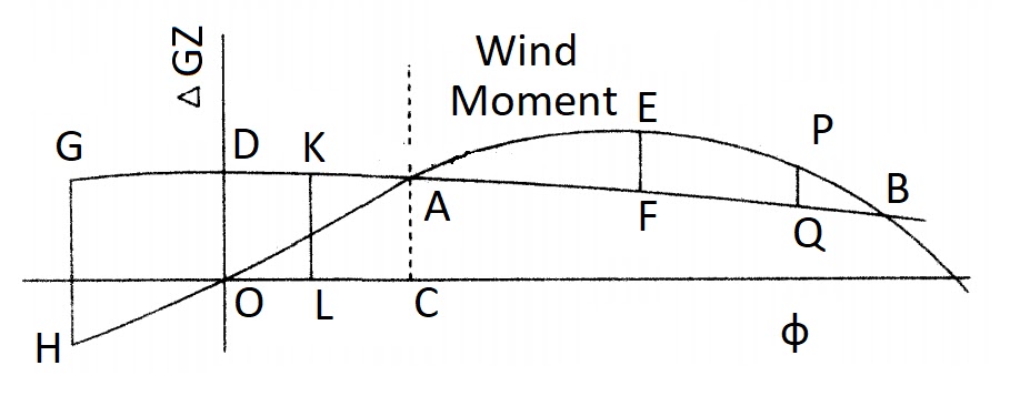
If the wind moment builds up or is applied slowly the ship will heel to an angle represented by A and in this condition the range of stability will be from A to B. The problem would then be analogous to that of the shifted weight. On the other hand, if the moment is applied suddenly, say by a gust of wind, the amount of energy applied to the ship as it heeled to A would be represented by the area DAGO. The ship would only absorb energy represented by area OAC and the remaining energy would carry it beyond A to some angle F such that
area AEF = area DAO.
Should F be beyond B the ship will capsize, assuming the wind is still acting.
A severe case for a rolling ship is if it is inclined to its maximum angle to windward and about to return to the vertical when the gust hits it. Suppose this position is represented by GH. The ship would already have sufficient energy to carry it to some angle past the upright, say KL. Due to damping this would be somewhat less than the initial windward angle. The energy put into the ship by the wind up to angle L is now represented by the area GDKLOH. The ship will continue to heel until this energy is absorbed, perhaps reaching angle Q.
Title E: Resistance
The total resistance:
Also called tow-rope resistance $\displaystyle \small \mathrm{R_t}$, of a ship may be divided into two main sections:
(a) frictional resistance $\displaystyle \small \mathrm{R_f}$ ,
(b) residuary resistances $\displaystyle \small \mathrm{R_r}$ ,
Hence $\displaystyle \small \mathrm{R_t\ =\ R_f+R_r }$
Frictional Resistance $\displaystyle \small \mathrm{R_f}$,
As the ship moves through the water, friction between the hull and the water causes a belt of eddying water adjacent to the hull to be drawn along with the ship, although at a reduced speed. The belt moves aft and new particles of water are continually set in motion, the force required to produce this motion being provided by the ship.
The frictional resistance of a ship depends upon:
(i) the speed of the ship
(ii) the wetted surface area
(iii) the length of the ship
(iv) the roughness of the hull
(v) the density of the water.
Wm Froude formula:
$\displaystyle \small \mathrm{R_t\ =\ f.S.V^n}$ Newton
where f is a coefficient which depends upon the length of the ship L, the roughness of the hull and the density of the water.
S is the wetted surface area in $\displaystyle \small \mathrm{m^2}$
V is the ship speed in knots
n is an index of about 1.825
The value of 'f' for a mild steel hull in sea water is given by
$\displaystyle \small \mathrm{f = 0.417+\frac{0.773}{L+2.862}}$
Thus 'f' is reduced as the length of the ship is increased. In a slow or medium-speed ship the frictional resistance forms the major part of the total resistance, and may be as much as 75% of $\displaystyle \small \mathrm{R_t}$,. The importance of surface roughness may be seen when a ship is badly fouled with marine growth or heavily corroded, when the speed of the ship may be considerably reduced.
Residuary Resistance
Residuary Resistance
(1) Resistance caused by the formation of streamlines around the ship, i.e due to the change in the direction of the water. If the water changes direction abruptly, such as round box barge, the resistance may be considerable, but in modern, well designed ships this should be very small.
(2) Eddy resistance caused by sudden change in form. Having a rectangular stern frame and single plate rudder can cause 5% of the total resistance of the ship. Well designed streamlined stern frame and fitting of a double plated rudder, the eddy resistance can be reduced to a negligible level.
(3) Resistance caused by the formation of wave as the ship passes through the water. In slow or medium-speed ships the wave-making resistance is small compared with the frictional resistance. At high speeds, however, the wave making resistance is considerably increased and may be 50 to 60% of the total resistance.
Use of the Using a bulbous bow can be effective emthod in reduction of this resistance. The wave produced by the bulb interferes with the wave produced by the stem, resulting in a reduced height of bow wave and consequent reduction in the energy required to produce the wave.
Residuary Resistances follow Froude's Law of Comparison:
The residuary resistances of similar ships are in the ratio of the cube of their linear dimensions if their speeds are in the ratio of the square root of their linear dimensions.
Thus
$\displaystyle \small \mathrm{\frac{R_{r1}}{R_{r2}}=\left ( \frac{L_1}{L_2} \right )^3\ \ if, \frac{V_{1}}{V_{2}}=\sqrt{\frac{L_1}{L_2}}}$
or
$\displaystyle \small \mathrm{\frac{R_{r1}}{R_{r2}}=\left ( \frac{\Delta _1}{\Delta _2} \right )\ \ if,\frac{V_{1}}{V_{2}}=\left ( \frac{\Delta _1}{\Delta _2} \right )^\frac{1}{6} }$
Thus at corresponding speeds:
$\displaystyle \small \mathrm{\frac{V_{1}}{\sqrt{L_1}}= \frac{V_2}{\sqrt{L_2}}}$
$\displaystyle \small \mathrm{\frac{V}{\sqrt{L}}}$ is known as the speed-length ratio.
It may therefore be seen that at corresponding speeds the wave-making characteristics of similar ships are the same. At high speeds the speed-length ratio is high and the wavemaking resistance is large. To give the same wavemaking characteristics, the corresponding speed of a much smaller, similar ship will be greatly reduced and may not be what is popularly regarded to be a high speed. A ship is therefore considered slow or fast in rela-tion to its speed-length ratio.
$\displaystyle \small \mathrm{\frac{V}{\sqrt{L}}}$ below 1.0 the ship is said to be slow (V in knots: L in m)
$\displaystyle \small \mathrm{\frac{V}{\sqrt{L}}}$ above 1.5 the ship is said to be fast.
Thus a speed of 15 knots would be regarded as slow for a ship 225 m long, but fast for a ship 100 m long.
The calculation of residuary resistance is usually based on the results of model experiments. A wax model of the ship is towed at its corresponding speed in a towing tank and the total resistance of the model is calculated and subtracted from the total resistance, leaving the residuary resistance. The residuary resistance of the model is then used to determine the residuary resistance of the ship.
Once the total resistance of the ship is known it is possible to determine the power required to overcome resistance. This is known as the effective power (ep) of the ship. The model is tested without appendages such as rudder and bilge keels. An allowance must therefore be made for these appendages and also the general disturbance of the water at sea compared with tank conditions. This allowance is known as the ship correlation factor (SCF).
The power obtained directly from the model tests is known as the effective power (naked)($\displaystyle \small \mathrm{ep_n}$). The true effective power is the $\displaystyle \small \mathrm{ep_n}$ multiplied by the ship correlation factor.
Admiralty Coefficient
Q. What is admiralty coefficient?
Ans:- Admiralty Coefficient:-
It is sometimes necessary to obtain an approximation to the power of a ship without resorting to model experiments, and several methods are available. One system which has been in use for several years is Admiralty Coefficient method. This is based on the assumption that for small variations in speed the total resistance may be expressed in the form:$\displaystyle \small \mathrm{R_{t} \alpha \rho SV^{n}}$
It was seen earlier that,$\displaystyle \small \mathrm{S\ \alpha\ \ \Delta ^{2/3}}$
Hence with constant density,$\displaystyle \small \mathrm{R_{t}\ \ \alpha\ \ \Delta ^{2/3}V^{n}}$
But Power$\displaystyle \small \mathrm{P \alpha\ \ R_{t} x V,\ \ also\ \ P \alpha\ \ \Delta ^{2/3}V^{n+1}}$
or, Power,$\displaystyle \small \mathrm{P= \frac{ \Delta ^{2/3}V^{n+1}}{Coefficient}}$
The coefficient is known as The admiralty coefficient.
originally this method was used to determine the power supplied by the engine. Since type of machinery vary considerably it is now considered that the relation between displacement, speed and shaft power (Sp) is of more practical value. Most merchant ships may be classed as slow or medium speed, and for such vessels and index n may be taken as 2. Thus
Admiralty Coefficient,$\displaystyle \small \mathrm{C=\frac{\Delta ^{2/3}V^{3}}{sp}}$
Where △ = displacement in tonne
V= ship speed in Knots
sp = Shaft power in kW
The Admiralty Coefficient may be regarded as constant for similar ships at their corresponding speeds. Values of C vary between about 350 & 600 for different ships, the higher values indicating more efficient ships.
For small changes in speed, the value of C may be regarded as constant for any ship at constant displacement.
At corresponding speeds,$\displaystyle \small \mathrm{V\alpha\ \ \Delta ^{1/6}}$
and $\displaystyle \small \mathrm{sp\ \alpha\ \ \Delta ^{2/3}V^{3}}$
thus,$\displaystyle \small \mathrm{sp\ \alpha\ \ \Delta ^{7/6}}$
Thus if the shaft power of one ship is known, the shaft power for a similar ship may be obtained at corresponding speed.
Fuel Coefficient and consumption
The fuel consumption of a ship depends on the power developed. The overall efficiency is measured in terms of the specific fuel consumption i.e consumption per unit of power, expressed in kg/h. Efficient diesel engines may have a specific fuel consumption of about 0.20 kg/kW h, while that for a steam turbine may be about 0.30 kg/kW h.

In the figure Between $\displaystyle \small \mathrm{V_1\ and\ V_2}$ the specific consumption may be regarded as constant for practical purposes, If the ship speed varies between these limits then,
Fuel consumption/unit time ∝ power developed(sp)
and since
$\displaystyle \small \mathrm{sp\ \alpha\ \Delta ^\frac{2}{3}V^3 }$ ,
or Fuel consumption/day = $\displaystyle \small \mathrm{ \frac{\Delta ^\frac{2}{3}V^3}{Fuel\ coeff.}\ tonne}$
Values of fuel coefficient vary between 40,000 and 1,20,000 the higher values indicate more efficient ships.
If the displacement and fuel consumption remain constant then,
$\displaystyle \small \mathrm{ \frac{Cons_1}{Cons_2}=\left (\frac{V_1}{V_2} \right )^3}$
The total fuel consumption for any voyage= dialy consumption x no. of days
Number of days ∝ Distance travelled/speed in Knots.
and dialy consumption ∝$\displaystyle \small \mathrm{ (Speed)^3}$
thus,
total fuel consumption of any voayge ∝ $\displaystyle \small \mathrm{ (speed)^3}$ x Distance travelled/speed in Knots.
or, total fuel consumption of any voayge ∝ $\displaystyle \small \mathrm{ (speed)^2}$ x Distance travelled
thus,
$\displaystyle \small \mathrm{\frac{Voy. Cons_1}{Voy. Cons_2}=\left (\frac{V_1}{V_2} \right )^2 \times \frac{D_1}{D_2}}$
A general expression for voyage consumption is:
$\displaystyle \small \mathrm{\frac{Voy. Cons_1}{Voy.Cons_2}=\left ( \frac{\Delta_1 }{\Delta_2 } \right )^\frac{2}{3} \times\left (\frac{V_1}{V_2} \right )^2 \times \frac{D_1}{D_2}}$
Important to note: the assumption is that the ship speed lies between $\displaystyle \small \mathrm{V_1\ and\ V_2}$. If the speed is reduced to $\displaystyle \small \mathrm{V_3}$ however, the specific consumption may be increased by Y%. In this case the daily consumption and voyage consumption are also increased by same percentage i.e Y% (as the SPOC increased).
Title F: Propellers.
1. Driving face:- The after side of a marine propeller is the driving face and is in the form of a helical screw. This screw is formed by a number of blades, from three to seven, set at an angle to the plane of rotation.
2. Diameter "D" :- The diameter of the propeller is the diameter of the circle or disc cut out by the blade tips.
3. Pitch "P" :- If the propeller is assumed to work in an unyielding fluid, then in one revolution of the shaft the propeller will move forward a distance which is known as the pitch. Pitch ratio "p", or face pitch ratio is the face pitch divided by the diameter. Thus p=P/D
4. Theoretical speed "$\displaystyle \small \mathrm{V_t}$": It is the distance the propeller would advance in unit time if working in an unyielding fluid. Thus if the propeller turns at N rev/min, . $\displaystyle \small \mathrm{V_t}$= P x N m/min or $\displaystyle \small \mathrm{\frac{PN60}{1852}}$ Knots.
5. Apparent slip($\displaystyle \small \mathrm{S_a}$ ): The ship speed "V" is normally less than the theoretical speed ($\displaystyle \small \mathrm{V_t}$ ). The difference between the two speeds is known as the apparent slip and is usually expressed as a ratio or percentage of the theoretical seed.
Apparent slip speed = $\displaystyle \small \mathrm{V_t-V}$ knots
Apparent slip = $\displaystyle \small \mathrm{\frac{V_t-V}{Vt}}$ x 100%.
If the ship speed is measured relative to the surrounding water, i.e. by means of a log line, the theoretical speed will invariably exceed the ship speed, giving a positive apparent slip. If, however, the ship speed is measured relative to the land, then any movement of water will affect the apparent slip, and should the vessel be travelling in a following current the ship speed may exceed the theoretical speed, resulting in a negative apparent slip.
6. Wake(w): In its passage through the water the ship sets in motion particles of water in its neighborhood, caused, as mentioned earlier, by friction between the hull and the water. This moving water is known as the wake and is important in propeller calculations since the propeller works in wake water. The speed of the ship relative to the wake is termed the Speed of advance ($\displaystyle \small \mathrm{V_a}$).
The wake speed is often expressed as a fraction of the ship speed.
Wake fraction $\displaystyle \small \mathrm{w =\frac{V - Va}{V}}$
The wake fraction may be obtained approximately from the expression:
$\displaystyle \small \mathrm{w =0.5C_b - 0.05}$
where $\displaystyle \small \mathrm{C_b}$ is the block coefficient.
7. Real slip or True slip is the difference between the theoretical speed and the speed of advance, expressed as a ratio or percentage of the theoretical speed. Real slip speed = $\displaystyle \small \mathrm{V_t-V_a}$ knots
Real slip = $\displaystyle \small \mathrm{\frac{V_t-V_a}{V_t}}$ x 100%.
The real slip is always positive and is independent of current.The line diagram below shows relation between the different speeds:.
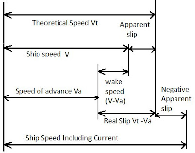 Projected Area “A”: It is the sum of the blade areas projected onto a plane which is perpendicular to the axis of the screw.
Developed Area is the actual area of the driving faces:
(a) clear of the boss $\displaystyle \small \mathrm{A_d}$ .
(b) including the boss area $\displaystyle \small \mathrm{A_b}$
Blade Area Ratio “BAR” is the developed area excluding the boss divided by the area of the circle cut out by the blade tips.
Projected Area “A”: It is the sum of the blade areas projected onto a plane which is perpendicular to the axis of the screw.
Developed Area is the actual area of the driving faces:
(a) clear of the boss $\displaystyle \small \mathrm{A_d}$ .
(b) including the boss area $\displaystyle \small \mathrm{A_b}$
Blade Area Ratio “BAR” is the developed area excluding the boss divided by the area of the circle cut out by the blade tips.
Real slip = $\displaystyle \small \mathrm{\frac{V_t-V_a}{V_t}}$ x 100%.
The real slip is always positive and is independent of current.The line diagram below shows relation between the different speeds:.
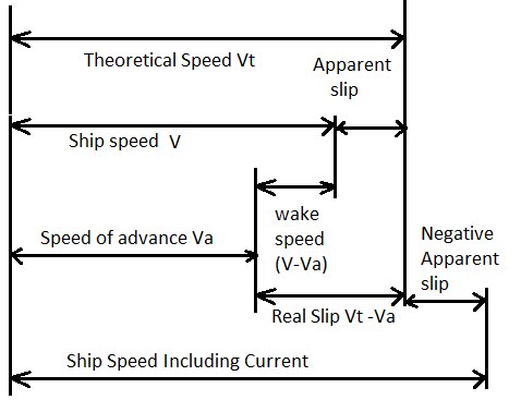
$\displaystyle \small \mathrm{\small BAR = \frac{A_d}{\frac{\pi }{4}xD^{2}}}$
Disc Area Ratio “DAR”: It is the developed area including boss divided by the area of the circle cut out by the blade tips.
$\displaystyle \small \mathrm{\small DAR = \frac{A_b}{\frac{\pi }{4}xD^{2}}}$
Thrust
Propeller Thrust -It is the force exerted by propellers on the water, which in turns pushes the ship to advance. Water on the propeller disc is received at the speed of advance and projected aft at the theoretical speed.
Thrust can be calculated as,
Thrust = mass x Acceleration
Mass of water passing through propeller per second is given by,
$\displaystyle \small \mathrm{m = \rho\times A\times P\times n\ kg}$
Where,
ρ = density
A = effective disc area
P = pitch
n = rps
Acceleration can be find as change in velocity per second,
$\displaystyle \small \mathrm{a = P.n - V_a}$
Also, slip $\displaystyle \small \mathrm{S = (P.n - V_a)/ P.n}$
Or, $\displaystyle \small \mathrm{P.n.S = P.n -V_a}$
Thus, a =P.n.S
Now, Thrust $\displaystyle \small \mathrm{T= \rho A.P.n\times P.n.S}$
Note that The thrust is proportionally increasing with slip
Also Thrust power ($\displaystyle \small \mathrm{t_p}$ ) = thrust x speed of advance N-m/s (W)
We also know that,$\displaystyle \small \mathrm{ t_p = d_p\times propeller\ efficiency}$ .
Where $\displaystyle \small \mathrm{ d_p}$ = delivered power.
Relation between Powers
The power produced by the engine is the indicated power $\displaystyle \small \mathrm{ i_p}$ . The mechanical efficiency of the engine is usually between about 80% and 90% and therefore only this percentage of the $\displaystyle \small \mathrm{ i_p}$ is transmitted to the shaft, giving the shaft power $\displaystyle \small \mathrm{ s_p}$ or brake power $\displaystyle \small \mathrm{ b_p}$ .
$\displaystyle \small \mathrm{s_p\ or\ b_p=i_p\times mechanical\ efficiency}$
Shaft losses vary between about 3% and 5% and therefore the power delivered to the propeller, the delivered power $\displaystyle \small \mathrm{ d_p}$, is almost 95% of the $\displaystyle \small \mathrm{ s_p}$.
$\displaystyle \small \mathrm{ d_p=s_p\times transmission\ efficiency}$
The delivered power may be calculated from the torque on the shaft
$\displaystyle \small \mathrm{d_p\ =\ torque\ \times 2\pi n}$
The propeller has an efficiency of 60% to 70% and hence the thrust power $\displaystyle \small \mathrm{ t_p}$ is given by:
$\displaystyle \small \mathrm{ t_p = d_p\times propeller\ efficiency}$
The action of the propeller in accelerating the water creates a suction on the after end of the ship. The thrust exerted by the propeller must exceed the total resistance by this amount. The relation between thrust and resistance may be expressed in the form
$\displaystyle \small \mathrm{R_t = T (1 - t)}$
where t is the thrust deduction factor.
The thrust power will therefore differ from the effective power. The ratio of $\displaystyle \small \mathrm{e_p}$ to $\displaystyle \small \mathrm{t_p}$ is known as the hull efficiency which is a little more than unity for single screw ships and about unity
for twin screw ships.
$\displaystyle \small \mathrm{ e_p = t_p\times hull\ efficiency}$
In an attempt to estimate the power required by the machinery from the calculation of $\displaystyle \small \mathrm{e_p}$, a quasi propulsive coefficient QPC is introduced. This is the ratio of $\displaystyle \small \mathrm{e_p}$ to $\displaystyle \small \mathrm{d_p}$ and obviates the use of hull efficiency and propeller efficiency. The prefix quasi is used to show that the mechanical efficiency of the machinery and the transmission losses have not been taken into account.
$\displaystyle \small \mathrm{ e_p = d_p\times QPC}$
The true propulsive coefficient is the relation between the $\displaystyle \small \mathrm{ e_p }$ and the $\displaystyle \small \mathrm{ i_p}$ , although in many cases $\displaystyle \small \mathrm{ s_p}$ is used in place of $\displaystyle \small \mathrm{ i_p}$
$\displaystyle \small \mathrm{e_p = i_p\times propulsive\ coefficient}$
Or, $\displaystyle \small \mathrm{e_p = s_p\times propulsive\ coefficient}$ .
Measurement Of Pitch
If the propeller is assumed to have no forward motion, then a point on the blade, distance R from the centre of the boss will move a distance of 2𝝅R in one revolution. If the propeller is now assumed to work in an unyielding fluid, then in one revolution it will advance a distance of P, the pitch. The pitch angle θ may be defined as
$\displaystyle \small \mathrm{tan\theta =\small \frac{P}{2\pi R}}$
Pitch = tanθ x 2𝝅R.

the pitch of a propeller may be measured without removing the propeller from the ship, by means of a simple instrument known as a pitchometer. One form of this instrument consists of a protractor with an adjustable arm. The face of the boss is used as a datum, and a spirit level is set horizontal when the pitcho-meter is set on the datum. The instrument is then set on the propeller blade at the required distance from the boss and the arm containing the level moved until it is horizontal, a reading of pitch angle or pitch may then be read from the protractor at the required radius.

the pitch of a propeller may be measured without removing the propeller from the ship, by means of a simple instrument known as a pitchometer. One form of this instrument consists of a protractor with an adjustable arm. The face of the boss is used as a datum, and a spirit level is set horizontal when the pitcho-meter is set on the datum. The instrument is then set on the propeller blade at the required distance from the boss and the arm containing the level moved until it is horizontal, a reading of pitch angle or pitch may then be read from the protractor at the required radius.
An alternative method is to turn the propeller until one blade is horizontal. A weighted cord is draped over the blade at any given radius. A batten is placed horizontally at the lower edge of the blade with the aid of a spirit level. The distances AB and BC are then measured. θ is the pitch angle, and $\displaystyle \small \mathrm{tan\theta =\frac{BC}{AB}}$ But, Pitch = tanθ x 2𝝅R,
$\displaystyle \small \mathrm{\small Pitch=\left ( \frac{BC}{AB} \right )x2\pi R}$

the pitch of a propeller may be measured without removing the propeller from the ship, by means of a simple instrument known as a pitchometer. One form of this instrument consists of a protractor with an adjustable arm. The face of the boss is used as a datum, and a spirit level is set horizontal when the pitcho-meter is set on the datum. The instrument is then set on the propeller blade at the required distance from the boss and the arm containing the level moved until it is horizontal, a reading of pitch angle or pitch may then be read from the protractor at the required radius.

the pitch of a propeller may be measured without removing the propeller from the ship, by means of a simple instrument known as a pitchometer. One form of this instrument consists of a protractor with an adjustable arm. The face of the boss is used as a datum, and a spirit level is set horizontal when the pitcho-meter is set on the datum. The instrument is then set on the propeller blade at the required distance from the boss and the arm containing the level moved until it is horizontal, a reading of pitch angle or pitch may then be read from the protractor at the required radius.
An alternative method is to turn the propeller until one blade is horizontal. A weighted cord is draped over the blade at any given radius. A batten is placed horizontally at the lower edge of the blade with the aid of a spirit level. The distances AB and BC are then measured. θ is the pitch angle, and $\displaystyle \small \mathrm{tan\theta =\frac{BC}{AB}}$ But, Pitch = tanθ x 2𝝅R,
$\displaystyle \small \mathrm{\small Pitch=\left ( \frac{BC}{AB} \right )x2\pi R}$
Cavitation
The thrust of a propeller varies approximately as the square of the revolutions. Thus as the speed of rotation is increased there is a considerable increase in thrust. The distribution of pressure due to thrust over the blade section is approximately.
The net pressure at any point on the back of the blade is the algebraic sum of the atmospheric pressure, water pressure and negative pressure or suction caused by the thrust. When this suction is high at any point, the net pressure may fall below the vapour pressure of the water at water temperature, causing a cavity or bubble to form on the blade. This cavity is filled with water vapour and with air which disassociates from the sea water. As the blade turns, the bubble moves across the blade to a point where the net pressure is higher, causing the cavity to collapse. The forming and collapsing of these cavities is known as cavitation.
When the cavity collapses, the water pounds the blade material, and since the breakdown occurs at the same position each time, causes severe erosion of the blades and may produce holes in the blade material several mm deep. Cavitation also causes reduction in thrust and efficiency, vibration and noise. It may be reduced or avoided by reducing the revolutions and by increasing the blade area for constant thrust, thus reducing the negative pressure. Since cavitation is affected by pressure and temperature, it is more likely to occur in propellers operating near the surface than in those deeply submerged, and will occur more readily in the tropics than in cold regions.
..
Title G: Rudder Theory.
Centre of rotation or pivot point
Q. Centre of rotation. What is the name of that point. Pivot point.
Ans:- Pivot point is the point which trace the turning curve of a ship.
It is located in the fore section of the ship, aftwards of the stem at 1/6-1/3 of ship’s length. In general, position of the pivot point is located:
- in the horizontal plane of the drifting center, on the vertical line of gravity center of the vessel, when:
- the vessel is stationary with rudder zero, she has speed through the water and zero speed over the ground (at anchor in current);
- vessel is moving straight forward or backward, with rudder midship; - the vessel has speed over the ground and zero speed through the water (ship is dead in the water, she is drifted by current in calm water);
- position of the pivot point depends of the position of drifting center and this depends of the movement and its sense.
The vertical of the pivot point is the axis in respect with, during turning manoeuvre (or altering the course), the forces which act on the vessel induce the turning moments. The magnitude of these moments depends of the magnitude of the forces and the distances between positions of the application points of them and the axis of the pivot point. Usually, it (the pivot point) is moving forward when the vessel is moving ahead and aftwards during astern moving and it is stabilizing at about 25% of ship’s length or ¼ of ship’s length from stem or stern. For a stopped (without movement in respect with the water) at zero trim, in calm water and in absence of the wind, the pivot point coincides with gravity center of the vessel.
Under propulsion force and the resistance of the water, the pivot point moves forward. One can consider with certain approximation, that at a stable speed, the pivot point is at 25% or 1/4L from fore. During astern moving, the pivot point will be stabilized at about 25% or 1/4L from aft. Although not intended, some publications may give the impression that the pivot point moves right aft with sternway. This is clearly not correct and can sometimes be misleading. It should also be stressed that other factors such as acceleration, shape of hull and speed may all affect the position of the pivot point. The pivot point is defined also: that position aboard the vessel about which the ship rotates when turning.
In conventional vessels, the pivot point was approximately one third (1/3) of the ship’s length, measured from forward, when moving ahead. It should be noted that when the vessel goes to anchor the pivot point moves right forward and effectively holds the bow in one position. Any forces acting on the hull, such as from wind or current, would cause the vessel to move about the hawse pipe position. As a rule, close to the pivot point is placed the navigation bridge. The position of this point is determinate by ship’s gravity center position G and application point C of the rudder resistance, during moving of the vessel ahead or astern. Moving ahead, the pivot point is forward in respect with gravity center and moves more forward with the increasing speed; moving astern, it is behind gravity center and moves aftwards as the speed increase astern.
Title H: Definition of common terms
Beam:- A rolled steel section supporting the deck and positioned athwartship.
Beam knee:- A metal plate joining the deck beam and the frame at the ship's side.
Bilge Keel:- A projected off set bulb plate at right angled to the bilge radius region welded to a doubler plate on the ship shell, extending about half the ship's length only in the mid ship region in order to minimise roll motion.
Boot topping:- The area of ship's side plating in the region of load lines. It is the hull area which is most susceptible to corrosion.
Breast hook:- A horizontal flat plate which stiffens the stem structure.
Cable stopper :- A device used to hold the anchor cable in place while the ship is at anchor or the anchor is fully housed.
Dead weight tonnage:- The difference in tonnes between the displacement of ship in water of relative density of 1.025 and the load water line corresponding to the assigned summer freeboard and the lightweight of the ship.
Fair lead:- An item of mooring equipment which is used to maintain or change the direction of a rope or wire in order to provide a straight lead to a winch drum.
Free board :- The vertical distance from the summer load waterline to the top of the freeboard deck plating, measured at the ship's side amidship.
Garboard strake:- The bottom shell plating on either side of the keel plate.
Girder:- A continuous stiffening member which runs fore and aft in a ship to support the deck.
Gross tonnage:- The total of under deck tonnage ( a measure of the volume) and tonnage of any tween deck spaces between and second and upper deck, any enclosed spaces above the upper deck, any excess of hatch way over 0.5% of the gross tonnage and optionally any engine light & air spaces on or above the upper deck.
Gun wale:- The upper edge of a ship's side where the sheet strake meets the deck plating.
Guset plate :- A bracket plate usually positioned in a horizontal or almost horizontal plane.
Hatch Coaming:- vertical plating which surrounds a hatch opening. Its height is determined by the Merchant ship (load line) Rules 1968. The hatch cover rests, and is secured, on the top of the hatch coaming.
Hawse pipe:- A thick section pipe through which the anchor cable passes from the forecastle deck to the ship's side. A doubling plate is fitted around it at the forecastle deck and a chafing ring at the ship's side.
Hogging:- The condition of a floating ship when the distribution of weight and buoyancy along its length is such that the buoyancy amidship exceeds the weight.
Hull efficiency:- The ration of thrust power to effective power, which is usually a value greater than one.
Inclining experiment:- An experiment, conducted on an almost completed ship, in order to determine the vertical position of the center of gravity. The ship is inclined or healed by moving weight transversely across the deck.
Initial stability:- The stability of a vessel in the upright condition which is determined by the metacentric height, GM. If the metacentre, M, is above the center gravity, G, the GM is said to be positive and the vessel is stable.
Light weight:- The displacement of a ship in metric tonnes without cargo, fuel, lub oil, ballast water, fresh water, feed water, consumable store, passanger, crew and their effects
Net tonnage:- A measure of the useful capacity of a ship. It has previously been found by deducing the volume of space necessary for the propulsion and operation of the ship. e.g accommodation equipment and machinery spaces, from the gross tonnage. The international convention on tonnage measurement of ships, 1969, requires the use of a formula related to the volume of cargo carrying spaces.
Panting:- The in & out movement of a ship's plating.
Panting beam:- An athwartships structural element which is fitted at alternate frame space and bracketed to the panting stringers.
Panting stringers:- Stringers which are fitted at about two meter intervals below the lowest deck in the forward region to strengthen the ship's side plating against panting.
Permissible length:- the length between bulkheads on a ship in order to ensure that it will remain afloat in one or more, compartments are flooded. The permissible length is some fraction of the floodable length. The fraction is called the factor of subdivision.
Racking:- The transverse distortion of ship's structure due to acceleration and deceleration during rolling. it is greatest when the ship is in a light or ballast condition.
Registered tonnage:- The tonnage value which is stated on the certificate of Registry.
Reserve buoyancy:- Intact volume of enclosed spaces which provide buoyancy in addition to that required by a vessel to float. It is a consideration in the assignment of freeboard to a ship.
Righting lever:- The length of the lever arm between a vertical extended up from the center of gravity to the vertical extended up to from the center of buoyancy of a ship. it is referred to as GZ and is the criterion used to determine stability at large angles of inclination.
Rise of floor:- The height of the bottom shell plating above the baseline. It is measured at the moulded beam line of a ship.
Sheer:- The curvature of the deck in a longitudinal direction. it is measured between the deck height at midships and the particular point on the deck.
Sheer Strake:- The strake or plate of side plating nearest to the deck. it is usually in thickness or a higher tensile steel is used because of high bending stresses experienced.
Shell expansion:- A plan which shows the position and thickness of all the plates which comprise the shell plating of a ship. The extent of each prefabricated unit of the ship will also normally be shown.
Spurling Pipe: A heavy plate pipe which is fitted at entrance to the chain locker to lead the anchor cable in and out. A solid round bar chaffing ring is fitted on the lower edge inside the chain locker.
Stanchion:- a vertical metal post which forms part of handrail or a protective barrier.
Statical stability:- the ability of a vessel to return to the upright position when inclined by some force.
Strake:- A continuous line of plating extending fore and aft over the length of a ship.
Stringer plate:- The out board strake of plating on any deck.
Tail Shaft:- The final length of shafting to which the propeller is attached. It has a flanged face where it joins the intermediate shafting. The other end is teppered to suit a similar tapper on the propeller boss. it is also called propeller shaft.
Tonnage:- A measure of the internal capacity of a ship where 100 cubic feet or 2.83 cubic meters represent one tonne. Two values are normally given for a ship, net tonnage and gross tonnage.
Torsion box:- A rectangular cross-section girder running fore and aft on either side of a container ship. it extends from the ship's side to the cargo hold openings.
Transom stern:- A flat stern construction of almost triangular section. it is simpler to construct when compared with a cruiser stern and also gives and increased after deck area.
Wake:- The water which is in motion at the stern of a ship as a result of a result of a ship's movement.
Wake fraction:- The ratio of the wake speed to the speed of advance or the ship speed. The Froude wake fraction uses the speed of advance and the Taylor Wake fraction the ship speed.
Web:- A flat plate with a flanged or stiffened.
Yawing:- The motion of a ship when it is rotating about a vertical axis.
Title I: Questions and Answers
Question 1: With reference to Container Ships : (A) Describe the problem of Parametric Roll ; (B) Explain how this problem is suitably addressed in the design and operation of the vessel. (C) Describe possible methods for improving the stability of these vessels. (D)Actions to be taken to mitigate Parametric rolling.
Answer:
(A) Parametric rolling: This type of rolling is particularly noticed in large container ships because of their special design. Such ships require large length and breadth of the upper deck for loading substantial number of containers. They also require narrow streamlined hull design in the underwater part of the ship for attaining high speed. The flare of the ship at the bows and stern is considerably more than other ships of similar size.
When such a ship experiences long waves from ahead or astern resulting in pitching motion, the crest of the wave will come under the midship part of the ship and the bows and stern will lie in the trough. This will cause a momentary reduction of the draft, underwater volume, water-plane area, moment of Inertia of the water-plane, KB, BM and finally the KM of the ship, thus reducing the GM of the ship for a short duration. In case the GM becomes -ve during the above pitching motion, unstable equilibrium will cause an angle of loll. Once the wave passes under the ship, the original stabile equilibrium status will be restored and angle of loll will be eliminated. Thus the ship will start rolling along with pitching due to head or stern waves. This is called Parametric rolling.
Parametric rolling motion: Parametric rolling motion or "auto parametrically excited motion" as it should be called and its associated dangers came into prominence with the advent of large container ships and the peculiarities of their design which allowed them have a larger deck area and a streamlined hull design for extra speed. E.g. these ships had a forward and aft flare exceeding 45° as opposed to 30° in older designs. This flare coupled with a flat aft shape resulted in considerable change of righting lever GZ with the draft of the vessel. As a result when a large wave crest came amidships the troughs encountered narrow bow and sterns (Due to increased flare), and a resultant drop in KB and KM resulting in a temporary negative GM situation until the crest moved away from mid ships and moved to the bow and stern section. In this condition if the GM is plotted against the position of the crest as it moves down the bow an U shaped curve results wherein the GM can go below zero. With reduced or negative righting levers large roll angles up to 40 - 50° and extreme pitching may result with this condition of ship movement termed parametric rolling.
Parametric rolling motion: Parametric rolling motion or "auto parametrically excited motion" as it should be called and its associated dangers came into prominence with the advent of large container ships and the peculiarities of their design which allowed them have a larger deck area and a streamlined hull design for extra speed. E.g. these ships had a forward and aft flare exceeding 45° as opposed to 30° in older designs. This flare coupled with a flat aft shape resulted in considerable change of righting lever GZ with the draft of the vessel. As a result when a large wave crest came amidships the troughs encountered narrow bow and sterns (Due to increased flare), and a resultant drop in KB and KM resulting in a temporary negative GM situation until the crest moved away from mid ships and moved to the bow and stern section. In this condition if the GM is plotted against the position of the crest as it moves down the bow an U shaped curve results wherein the GM can go below zero. With reduced or negative righting levers large roll angles up to 40 - 50° and extreme pitching may result with this condition of ship movement termed parametric rolling.
(B) As per ABS guide for parametric roll assesment:
a. The calculations and checks are done for design wave and ahead speed which will most likely lead to the development of parametric roll.
b. These conditions are: wave length equals ship length and ahead speed results in a frequency of encounter that is about twice the roll natural frequency.
c. If such a speed falls into the operational range of speeds, all further calculations are done for the above conditions.
d. If such speed does not fall into the operational range, the calculations are done for highest operational speed (design speed) and wave length equal to ship length.
e. Additionally, the calculations are to be done for the wave length leading to encounter frequency about twice that of the roll natural frequency and the design speed.
f. The calculations include the following steps. Stability in waves is to be computed for a number of positions of wave crest along the hull, then maximal and minimal GM values are to be evaluated. Maximal GM value is expected when the wave trough is close to amidships and the minimum GM value is expected when the wave crest is close to (but not necessarily exactly at) amidships.
g. The difference between maximum and minimum values defines the amplitude of parametric excitation.
h. In order for the susceptibility criteria to be used, the parametric excitation is presented in the form of a value oscillating as sinusoidal function about the mean value, which is obtained by averaging the GM from the above-mentioned calculations. This averaged GM is used to evaluate ahead speed.
i. If any of these checks indicate susceptibly, the severity of parametric roll is to be checked with a simplified numerical procedure. j. Indicated severity is to be considered as a warning of a possible problem with parametric roll, which has to be addressed during further design. Sophisticated numerical simulations and model tests are to be considered.
k. Based on the results of the numerical simulations and model tests, operational guidance is to be developed.
(C) 1. Special attention is require for the stability of a container ship. Factors such as Alternating course with Big angle of Rudder, Towing by tugs at the scene of Berthing / Un-berthing, etc. should never ignore.
2. Course and speed can be altertered during rough sea conditions
3. Make a good stowage plan and maintain Safe loading, keeping GM positive and small.
While making stowage plan it should be observed that deviation from the safe criteria as specified in ships class approved loading manual should not take place.
4. Upon completion of the repair works the vessel it is essential, that adequate function tests and inspections are carried out under the supervision of superintendent of all safety systems and systems that had been disturbed during the repair period.
A suitable checklist is to be compiled in order to ensure that all critical equipment, such as key navigational, propulsion, steering, cargo, ballast, fire and gas detection systems are tested.
5. At drydocks the replacement of bottom plugs, anodes, sea chest valves correctly set and ensuring echo sounder and Doppler transducers are cleared and written confirmation that all personnel are adequately tested before departure.
6. Damage Control Information (DCI) which is a part of onboard documentation, should be clear and easy to understand. It should not include more information than this directly relevant to damage control, and should be provided in the working language of the ship.
The DCI is intended to provide the ship’s officers with clear information on the ship’s watertight subdivision and equipment related to maintaining the integrity of the watertight boundaries, so that in the event of ship damage causing flooding proper precautions can be taken to prevent progressive flooding. The DCI should consist of: Damage Control Plan, Damage Control Manual, External Watertight Integrity Plan and Internal Watertight Integrity Plan.
(D) Actions to be taken to mitigate Parametric rolling:
1. By increasing speed there is a risk of increasing panting and pounding stresses on the bows of the ship, which could cause structural damage.
2. Altering course so as to increase the angle between the direction of waves and ship's head, will reduce the possibility of loss of GM.
1. By increasing speed there is a risk of increasing panting and pounding stresses on the bows of the ship, which could cause structural damage.
2. Altering course so as to increase the angle between the direction of waves and ship's head, will reduce the possibility of loss of GM.
3. Best action will be to adopt zig-zag courses so that the mean course being followed will ultimately take the ship to its destination even though the distance and time period of voyage will increase. Increasing or reducing speed could adversely affect Parametric rolling.
Question 2: Describe briefly the significance of the factor of sub-division.
Answer: Factor of subdivision: - An arbitrary factor used in computing allowable floodable length of ships after damage, set up by regulations and international convention.
The factor of subdivision shall depend on the length of the ship , and for a given length shall vary according to the nature of the service , for which the ship is intended. It shall decrease in a regular and continuous manner as follows:
As the Length of the ship increases, and From a factor A, applicable to ships primarily engaged in the carriage of cargo , to a factor B, applicable to ships, primarily engaged to carriage of passengers.
The variations of the factors A and B shall be expressed by the following formula (i) and (ii) where L is the length of the ship as defined in regulation to ( length between perpendiculars)
$\displaystyle \small \mathrm{A= \frac{58.2}{L-60}+0.18}$ ( L = 131 m and upwards )-- (i)
$\displaystyle \small \mathrm{B= \frac{30.3}{L-42}+0.18}$ (L = 79m and upwards)-- (ii)
The above two factors A and B when combined mathematically with the criterion of Service ( $\displaystyle \small \mathrm{C_s}$ ) gives the appropriate factor of subdivision.
Criterion of Service:-
For a ship of given length the appropriate factor of subdivision shall be determined by the criterion of service numeral or criterion Numeral, as given by the following formula (iii) and (iv) where :
$\displaystyle \small \mathrm{C_s}$ = Criterion Numeral
L = Length of the ship in meters.
M = The volume of the machinery space (cubic meters).
P = The whole Volume of the passenger spaces below the margin line (cubic meters).
V = The whole Volume of the Ship below the margin Line (cubic meters)
P1 = KN
Where:
N = the number of passengers for which the ship is to be certified, and
K = 0.056 L
Where the value of KN is greater than the sum of P and the whole volume of the actual passenger spaces above the margin line, P1 is the sum or two-third KN, whichever is greater.
When P1 is greater than P;
$\displaystyle \small \mathrm{C_s=72\frac{M+2P1}{V+P1-P}}$ --
--(iii)
else
$\displaystyle \small \mathrm{C_s=72\frac{M+2P}{V}}$ --(iv)
$\displaystyle \small \mathrm{C_s=72\frac{M+2P}{V}}$ --(iv)
Question 3: Describe the effect of cavitation’s on the propeller blades.
Answer: a. Cavitation can causes severe erosion of the blades and may produce holes in the blade material of several mm deep.
b. Cavitation also causes reduction in thrust and efficiency, vibration and noise.
c. It may be reduced or avoided by reducing the revolutions and by increasing the blade area for constant thrust, thus reducing the negative pressure.
d. Since cavitation is affected by pressure and temperature, it is more likely to occur in propellers operating near the surface than in those deeply submerged, and will occur more readily in the tropics than in cold regions.
Question 4: Describe the stability requirements of a ship for dry-docking.
Answer: The requirements for safe stability during docking and undocking as follows:
1. The mean draft selected should as per the yard recommendation and be such that the critical GM on docking is positive and should be varified by master at loadicator.
2. When docking the ship is slightly trimmed by the stern so that the stern block touches the stern frame first. The stern frame consist of sole plate engulfed by keel plate prepared by casting specially and it is the strongest point in a ship's hull.
3. The ship should always be upright during docking and undocking. This requires monitoring of the inclinometers during the docking operation and take suitable corrective action by transferring water or bunkers as required.
4. No water should he pumped in or out of the ship as that would affect the selected displacement of the ship.
5. Do not exceed the recommended mean draft of the ship
6. Do not exceed the recommended stern trim.
7. Ensure all bilges and bilge tanks are dry and there is no unaccounted water on hoard.
8. Soundings of all tanks containing F.W. Ballast. F.O. DO. and LO. must he recorded and must be the same for each tank at the time of undocking. If F.W. is consumed during the stay in dry dock. the consumed amount must be replenished into the tank before undocking.
Question 5: Describe how thrust power is determined.
Answer:Thrust Power can be determined by the relation:
$\displaystyle \small \mathrm{t_p = \frac{e_p}{hull\ efficiency}}$
$\displaystyle \small \mathrm{e_p}$ is the effective power it can be calculated by using the following relations:
$\displaystyle \small \mathrm{ e_p = d_p\times QPC}$
or, $\displaystyle \small \mathrm{e_p = s_p\times propulsive\ coefficient}$
where; $\displaystyle \small \mathrm{d_p}$ is delivered power can be calculated as $\displaystyle \small \mathrm{d_p= torque\times 2\pi n}$.
QPC = quasi propulsive coefficient.
$\displaystyle \small \mathrm{s_p}$ is shaft power can be calculated as $\displaystyle \small \mathrm{s_p=i_p\times mechanical\ eff.}$.
$\displaystyle \small \mathrm{i_p}$ is indicated power of engine.
Alternatively Thrust Power can be determined by;
$\displaystyle \small \mathrm{t_p = d_p\times propeller\ efficiency}$
Question 6: With reference to Roll-on Roll-off ferries –
A. Describe the problem of free surface effect;
B. Explain how it is intended that water should be cleared from car or cargo decks;
C. Describe possible methods for improving the stability and survivability of these vessels.
Answer: (A) When a tank on board a ship is not completely full of liquid, and the vessel heels, the liquid moves across the tank in the same direction as the heel. The centre of gravity of the ship moves away from the centre line, reducing the righting lever and increasing the angle of heel. This is called free surface effect.
Transverse bulkheads are incorporated to maintain the structural strength and damaged stability or water-tight integrity of the ship, in case of flooding of any of the compartments. Due to absence of subdivisional bulkheads, the water progresses along the length of the ship. This not only causes the ship to lose its inherent buoyancy, but adversely affects its stability because of increasing free surface effect. Ship loses its stability more rapidly than any other ship. Also the RO-RO vessels have large external openings below freeboard deck i.e bow and stern doors.
(B) The best method of clearing the water collected on the car decks is with the aid of an adequate number of medium sized scuppers positioned all along the sides of the deck leading straight to the sea just the necessary bends. Apart from this two large scuppers to be led to the machinery space bilge wells from where the water can be pumped out by large capacity bilge pumps.
(C) (i) The stability of the ship can be improved by fitting buoyant side appendages named sponsons at the load water plane.
(ii) The openings below water deck should be minimum, only one opening in the stern should be arranged.
(iii) Watertight doors can be used to perform the job of Transverse watertight bulkheads.
(iv) Additional doors can be used after the foreward door.
Question 7: What is meant by the Admiralty Coefficient and the Fuel Coefficient?
Answer: Admiralty Coefficient:-
Admiralty Coefficient,$\displaystyle \small \mathrm{C=\frac{\Delta ^{2/3}V^{3}}{sp}}$
The Admiralty Coefficient may be regarded as constant for similar ships at their corresponding speeds. Values of C vary between about 350 & 600 for different ships, the higher values indicating more efficient ships.
Fuel Coefficient and consumption:-
It is sometimes necessary to obtain an approximation to the power of a ship without resorting to model experiments, and several methods are available. One system which has been in use for several years is Admiralty Coefficient method. This is based on the assumption that for small variations in speed the total resistance may be expressed in the form:$\displaystyle \small \mathrm{R_{t} \alpha \rho SV^{n}}$
It was seen earlier that,$\displaystyle \small \mathrm{S\ \alpha\ \ \Delta ^{2/3}}$
Hence with constant density,$\displaystyle \small \mathrm{R_{t}\ \ \alpha\ \ \Delta ^{2/3}V^{n}}$
But Power$\displaystyle \small \mathrm{P \alpha\ \ R_{t} x V,\ \ also\ \ P \alpha\ \ \Delta ^{2/3}V^{n+1}}$
or, Power,$\displaystyle \small \mathrm{P= \frac{ \Delta ^{2/3}V^{n+1}}{Coefficient}}$
The coefficient is known as The admiralty coefficient.
originally this method was used to determine the power supplied by the engine. Since type of machinery vary considerably it is now considered that the relation between displacement, speed and shaft power (Sp) is of more practical value. Most merchant ships may be classed as slow or medium speed, and for such vessels and index n may be taken as 2. Thus
Admiralty Coefficient,$\displaystyle \small \mathrm{C=\frac{\Delta ^{2/3}V^{3}}{sp}}$
Where △ = displacement in tonne
V= ship speed in Knots
sp = Shaft power in kW
The Admiralty Coefficient may be regarded as constant for similar ships at their corresponding speeds. Values of C vary between about 350 & 600 for different ships, the higher values indicating more efficient ships.
For small changes in speed, the value of C may be regarded as constant for any ship at constant displacement.
At corresponding speeds,$\displaystyle \small \mathrm{V\alpha\ \ \Delta ^{1/6}}$
and $\displaystyle \small \mathrm{sp\ \alpha\ \ \Delta ^{2/3}V^{3}}$
thus,$\displaystyle \small \mathrm{sp\ \alpha\ \ \Delta ^{7/6}}$
Thus if the shaft power of one ship is known, the shaft power for a similar ship may be obtained at corresponding speed.
Fuel Coefficient and consumption:-
The fuel consumption of a ship depends on the power developed. The overall efficiency is measured in terms of the specific fuel consumption i.e consumption per unit of power, expressed in kg/h. Efficient diesel engines may have a specific fuel consumption of about 0.20 kg/kW h, while that for a steam turbine may be about 0.30 kg/kW h.
In the figure Between $\displaystyle \small \mathrm{V_1\ and\ V_2}$ the specific consumption may be regarded as constant for practical purposes, If the ship speed varies between these limits then,
Fuel consumption/unit time ∝ power developed(sp)
and since
$\displaystyle \small \mathrm{sp\ \alpha\ \Delta ^\frac{2}{3}V^3 }$ ,
or Fuel consumption/day = $\displaystyle \small \mathrm{ \frac{\Delta ^\frac{2}{3}V^3}{Fuel\ coeff.}\ tonne}$
Values of fuel coefficient vary between 40,000 and 1,20,000 the higher values indicate more efficient ships.
Question 8: Explain how the period of roll varies with –A. The amplitude of roll; B. The radius of gyration; C. The initial metacentric height; D. The location of masses in the ship.
Answer: Rolling
If ф is the inclination to the vertical at any instant, and the ship is stable, there will be a moment acting on it tending to return it to the upright. The value of this moment will be:
$\displaystyle \small \mathrm{\rho g\bigtriangledown \times GZ=\Delta \phi GM_T}$ for small angles.
$\displaystyle \small \mathrm{\rho g\bigtriangledown \times GZ=\Delta \phi GM_T}$ for small angles.

By Newton's laws, this moment will impart an angular acceleration. such that:
$\displaystyle \small \mathrm{\left ( \frac{\Delta k_x^2}{g} \right )\frac{d^2\phi }{dt^2}=-\Delta GM_T\phi }$
or, $\displaystyle \small \mathrm{\frac{d^2\phi }{dt^2}+\frac{g .GM_T}{K_x^2}\phi =0 }$
This is the standard differential equation denoting simple harmonic motion with a period T, defined by:
$\displaystyle \small \mathrm{T=2\pi \sqrt{\frac{K_x^2}{g .GM_T}}=\frac{2\pi K_x}{\sqrt{g .GM_T}}}$
where $\displaystyle \small \mathrm{K_x}$ is the radius of gyration about a fore and aft axis. This period is independent of 9 and such rolling is said to be isochronous. The relationship holds for most ships up to angles of about 10° from the vertical. It will be noted that the greater $\displaystyle \small \mathrm{GM_T}$ the shorter the period. A ship with a short period of roll is said to be stiff and one with a long period of roll is termed tender,: which is a slower motion and less unpleasant.
A. Amplitude of roll:- Amplitude is the maximum extent of a vibration or oscillation, measured from the position of equilibrium. From the expression above it is clear that the period of roll is independent of amplitude of roll. The amplitude of roll depend upon the applied heel moment and stability of the ship.
B. Radius of gyration:- From the expression of Period of roll it is clear that it is directly proportional to radius of gyration, thus by varying the radius of gyration, period of roll can be varied proportionally.
Value of radius of gyration varies with the displacement of cargo movement of cargo. If the cargo is concentrated in the centre compartment with wing tanks empty, the value of radius of gyration is small, hence small period of roll. So, the vessel will tend to return to initial position more quickly. But if cargo is concentrated in wing tanks, radius of gyration increases, leading to a large period of roll. So the vessel will tend to return to initial position slowly.
C. Initial Metacentric Height:- From the expression of Period of roll it is clear that it is inversly proportional to the square root of GM. When a ship has a comparatively large GM, the ship will have a comparatively short time period and will roll quickly and perhaps violently from side to side. When GM is small, period of roll will be longer.
D. Location of masses in the ship:- Distance of Location of masses from midship will affect the radius of gyration and which is directly proportional to the period of roll.
Vertical distance of masses is related with the metacentric height, masses are contracted in the lower hold cause a larger GM and the masses concentrated in the top deck causes smaller GM. Larger GM means smaller roll period from the expression of period of roll it can be seen thus the period of roll will increase.
Question 9: (a) What is free surface effect? How can be avoided or reduced. (b) Give the components of ships resistance while vessel is ‘enroute’.
Answer: (a) Free surface effect:If a tank is completely filled with liquid, it can be treated in exactly the same way as any other weight in the ship; that is, its weight can be regarded as being concentrated at its actual centre of gravity. In a tank which is only partly filled, the surface of the liquid is free to move and possesses inertia. The moment of inertia of this free surface about its own centre-line causes a virtual centre of gravity to appear at some height above it. The effect on the ship's stability will then be as if a weight, equal to the weight of the liquid in the tank, were raised from its position in the tank to the position of the virtual centre of gravity.
When a tank on board a ship is partially full of liquid, and the vessel heels, the liquid moves across the tank in the same direction as the heel. The centre of gravity of the ship moves away from the centreline, reducing the righting lever and increasing the angle of heel. Since the initial stability of a ship is usually measured in terms of metacentric height, it is useful to assume that the effect of a free surface of liquid is to raise the centre of gravity from G1 to G2, thus reducing the metacentric height of the vessel. GG2 is termed the virtual reduction in metacentric height due to free surface or the free surface effect.
Free surface effect GG2 = $\displaystyle \small \mathrm{ \frac{\rho i}{\Delta }}$
Where, ρ = Relative density of liquid inside the tank.
⛛ = Volume of displacement.
i = Second Moment of area of free surface about the centerline of the tank.
Methods for reducing or avoiding free surface effect:
(i) All tanks which are used for carrying liquid, shouldnot be left slack and to be pressed up tight.
(ii)While ballasting for the list correction always pressup the present tank and then start filling next tank. This to be followed in reverse while deballasting.
(iii)Tanks are to be constructed with more-divisions longitudinal and transversal divisions which reduces the free surface effect.
(iv) Lashing of heavy items and securing properly will reduce masses moving across. All suspended massed are to be stowed and secured.
(v)Pools are drained in bad Weather. Scuppers are ensured open and maintained free from blockages.
(vi) Vent line of the tanks shall be always kept in clear condition.
(vii) Tankers are built with centreline bulkhead and expansion trunks or Twin longitudinal bulkheads are to be used.
(b) The total resistance:
Also called tow-rope resistance $\displaystyle \small \mathrm{R_t}$, of a ship may be divided into two main sections:
(a) frictional resistance $\displaystyle \small \mathrm{R_f}$ ,
(b) residuary resistances $\displaystyle \small \mathrm{R_r}$ ,
Hence $\displaystyle \small \mathrm{R_t\ =\ R_f+R_r }$
Frictional Resistance $\displaystyle \small \mathrm{R_f}$,
As the ship moves through the water, friction between the hull and the water causes a belt of eddying water adjacent to the hull to be drawn along with the ship, although at a reduced speed. The belt moves aft and new particles of water are continually set in motion, the force required to produce this motion being provided by the ship.
The frictional resistance of a ship depends upon:
(i) the speed of the ship
(ii) the wetted surface area
(iii) the length of the ship
(iv) the roughness of the hull
(v) the density of the water.
Wm Froude formula:
$\displaystyle \small \mathrm{R_t\ =\ f.S.V^n}$ Newton
where f is a coefficient which depends upon the length of the ship L, the roughness of the hull and the density of the water.
S is the wetted surface area in $\displaystyle \small \mathrm{m^2}$
V is the ship speed in knots
n is an index of about 1.825
The value of 'f' for a mild steel hull in sea water is given by
$\displaystyle \small \mathrm{f = 0.417+\frac{0.773}{L+2.862}}$
Thus 'f' is reduced as the length of the ship is increased. In a slow or medium-speed ship the frictional resistance forms the major part of the total resistance, and may be as much as 75% of $\displaystyle \small \mathrm{R_t}$,. The importance of surface roughness may be seen when a ship is badly fouled with marine growth or heavily corroded, when the speed of the ship may be considerably reduced.
Residuary Resistance
(1) Resistance caused by the formation of streamlines around the ship, i.e due to the change in the direction of the water. If the water changes direction abruptly, such as round box barge, the resistance may be considerable, but in modern, well designed ships this should be very small.
(2) Eddy resistance caused by sudden change in form. Having a rectangular stern frame and single plate rudder can cause 5% of the total resistance of the ship. Well designed streamlined stern frame and fitting of a double plated rudder, the eddy resistance can be reduced to a negligible level.
(3) Resistance caused by the formation of wave as the ship passes through the water. In slow or medium-speed ships the wave-making resistance is small compared with the frictional resistance. At high speeds, however, the wave making resistance is considerably increased and may be 50 to 60% of the total resistance.
Use of the Using a bulbous bow can be effective emthod in reduction of this resistance. The wave produced by the bulb interferes with the wave produced by the stem, resulting in a reduced height of bow wave and consequent reduction in the energy required to produce the wave.
Residuary Resistances follow Froude's Law of Comparison:
The residuary resistances of similar ships are in the ratio of the cube of their linear dimensions if their speeds are in the ratio of the square root of their linear dimensions.
Thus
$\displaystyle \small \mathrm{\frac{R_{r1}}{R_{r2}}=\left ( \frac{L_1}{L_2} \right )^3\ \ if, \frac{V_{1}}{V_{2}}=\sqrt{\frac{L_1}{L_2}}}$
or
$\displaystyle \small \mathrm{\frac{R_{r1}}{R_{r2}}=\left ( \frac{\Delta _1}{\Delta _2} \right )\ \ if,\frac{V_{1}}{V_{2}}=\left ( \frac{\Delta _1}{\Delta _2} \right )^\frac{1}{6} }$
Thus at corresponding speeds:
$\displaystyle \small \mathrm{\frac{V_{1}}{\sqrt{L_1}}= \frac{V_2}{\sqrt{L_2}}}$
$\displaystyle \small \mathrm{\frac{V}{\sqrt{L}}}$ is known as the speed-length ratio.
It may therefore be seen that at corresponding speeds the wave-making characteristics of similar ships are the same. At high speeds the speed-length ratio is high and the wavemaking resistance is large. To give the same wavemaking characteristics, the corresponding speed of a much smaller, similar ship will be greatly reduced and may not be what is popularly regarded to be a high speed. A ship is therefore considered slow or fast in rela-tion to its speed-length ratio.
$\displaystyle \small \mathrm{\frac{V}{\sqrt{L}}}$ below 1.0 the ship is said to be slow (V in knots: L in m)
$\displaystyle \small \mathrm{\frac{V}{\sqrt{L}}}$ above 1.5 the ship is said to be fast.
Thus a speed of 15 knots would be regarded as slow for a ship 225 m long, but fast for a ship 100 m long.
The calculation of residuary resistance is usually based on the results of model experiments. A wax model of the ship is towed at its corresponding speed in a towing tank and the total resistance of the model is calculated and subtracted from the total resistance, leaving the residuary resistance. The residuary resistance of the model is then used to determine the residuary resistance of the ship.
Once the total resistance of the ship is known it is possible to determine the power required to overcome resistance. This is known as the effective power (ep) of the ship. The model is tested without appendages such as rudder and bilge keels. An allowance must therefore be made for these appendages and also the general disturbance of the water at sea compared with tank conditions. This allowance is known as the ship correlation factor (SCF).
The power obtained directly from the model tests is known as the effective power (naked)($\displaystyle \small \mathrm{ep_n}$). The true effective power is the $\displaystyle \small \mathrm{ep_n}$ multiplied by the ship correlation factor.
Question 10: Describe how the force on the ship’s bottom and the GM vary when grounding takes place.
Answer: Grounding:- when a ship runds ashore her metacentric height will decrease or become negative as in drydocking, but the exact effect of this on her stability is almost unpredictable. It will very according to the nature of the ground, how the ship is placed on the bottm, what damage she has sustained and the nature and state of the tides. In practice, we can only attempt to get the ship afloat again as soon as possible, if it appears safe to do so.
When a ship' is dry docked, her support has to be transferred from the water to the keel blocks and shores. She may be considered safe whilst she is waterborne, or once the shores have been set up, but there is a danger that she may become unstable during the intervening period. which is often termed the "critical period". Whilst the dock is being pumped out, the ship at first sinks bodily as the water-level falls, but as soon as she touches the keel blocks she stops sinking and the water falls around her. She thus loses displacement so that weight, equal to the amount of the lost displacement, is transferred to the blocks. As far as the ship's stability is concerned, this weight is equivalent to a force acting vertically upwards at the keel and it will decrease the metacentric height. The latter must, sooner or later, become negative and if this were to happen before the shores were properly set up, the ship might capsize in the dock. It is thus of the utmost importance to keep full control of the ship, during the critical period and to get the s~ores set up as soon as possible. To assist in this, it is usual to have the ship trimmed a little by the stern when she enters the dock, so that the heel of the stern post is the first part to touch the blocks. As soon as the ship's stern touches the blocks the upward force, 'P' comes into existance. This force is small at first, but gradually increases as the water level falls and ship's bow comes down. The advantage of this is that the decrease in metacentric height, caused by the force P, is more gradual than it would be if the ship suddenly sat flat on the blocks fore and aft, so that we have more control in the ship's stability. Also, though the shores cannot be set up before the ship comes down flat on the blocks, we can start to put-in the after shores loosely as soon as the stern touches. By the time that the ship is right down on the blocks a large number of shores are already in place, so that the remainder can be put in all up with the minimum of delay. This decreases the risk of the ship falling in the dock. it is important to have the ship upright when she enters a dry-dock. If she were not, this could be due to one of the two causes: a negative metacentric height, or the weights on board not being symmetrical about the centre-line. In the first case, the ship would be certain to fall over as soon as her keel touched the blocks. In the second, she might fall over at some time during the critical period on account of the excess of weight on one side. Before the ship is floated again, it is very important to check any weights which may have been shifted whilst she is in the dock; otherwise we may have a similar effect to the above whilst the dock is being filled. In this respect, do not forget to make sure that boilers have not been filled or emptied, or to check-up on any weights shifted in the engine-room. The procedure of dry docking is, briefly, as follows. As soon as the ship enters the dock she usually comes under the control of the foreman carpenter or shipwright, who manoeuvres her into the position requires. The dock gates are then closed and pumping-out commences. When the ship's stern is nearly on the blocks, pumping is stopped whilst the ship is aligned so that her centre-line is exactly over them. Pumping is then resumed slowly until the stern touches the blocks, when the after shores are put-in loosely. As the ship settles down, more shores are put-in, working from aft forward, and as soon as the keel comes flat on the blocks any remaining shores are put in place and all are set-up as quickly as possible. The heads of shores should always be placed on frames and not between them, in order to eliminate the risk of denting the ship's plating. Once the shores have been set-up, pumping is continued quickly until the dock is dry. The following formula will give the ship's metacentric height at any time during the process of drydocking:- Where P = the force acting upwards through the keel. KM = height of the metacentre on entering the dock. W = ship's displacement on entering dock. $New GM = Old GM-\frac{P\times KM}{W}$ The force P is the difference between the displacement of the ship on entering the dock and her displacement at the time for which we wish to calculate her GM. After the ship has come flat on the blocks, this calculation is quite simple, since two displacements will be those for the respective mean draughts: that is:- P = displacement at original draught - displacement at new draught if the displacemnt has decreased much, it may cause M to rise appreciably. If so, we would add a correction of $MM_1(1-\frac{P}{W})$ to the new GM. It is more difficult to find P during the citical period, after the ship's stern has touched the blocks, but before she come flat on them. The most dangerous part of this period, and hence the one with which we are most concerned, occures at the instant before the ship takes the blocks fore and aft. For this instant, P can be found approximately by the following formula:- where t= the trim, in cms, on entering the dock. l = the distance between the after block and the COF. $P=\frac{MCT1cm\times t}{l}$
Question 11: With reference to fixed pitch propellers; Explain Propeller Slip and Propeller Thrust.
Answer: Propeller slip or Real slip or True slip is the difference between the theoretical speed and the speed of advance, expressed as a ratio or percentage of the theoretical speed. Real slip speed = $\displaystyle \small \mathrm{V_t-V_a}$ knots
Real slip = $\displaystyle \small \mathrm{\frac{V_t-V_a}{V_t}}$ x 100%.
The real slip is always positive and is independent of current.
Real slip = $\displaystyle \small \mathrm{\frac{V_t-V_a}{V_t}}$ x 100%.
The real slip is always positive and is independent of current.
Propeller Thrust -It is the force exerted by propellers on the water, which in turns pushes the ship to advance. Water on the propeller disc is received at the speed of advance and projected aft at the theoretical speed.
Thrust can be calculated as,
Thrust = mass x Acceleration
Mass of water passing through propeller per second is given by,
$\displaystyle \small \mathrm{m = \rho\times A\times P\times n\ kg}$
Where,
ρ = density
A = effective disc area
P = pitch
n = rps
Acceleration can be find as change in velocity per second,
$\displaystyle \small \mathrm{a = P.n - V_a}$
Also, slip $\displaystyle \small \mathrm{S = (P.n - V_a)/ P.n}$
Or, $\displaystyle \small \mathrm{P.n.S = P.n -V_a}$
Thus, a =P.n.S
Now, Thrust $\displaystyle \small \mathrm{T= \rho A.P.n\times P.n.S}$
Note that The thrust is proportionally increasing with slip
Also Thrust power ($\displaystyle \small \mathrm{t_p}$ ) = thrust x speed of advance N-m/s (W)
We also know that,$\displaystyle \small \mathrm{ t_p = d_p\times propeller\ efficiency}$ .
Where $\displaystyle \small \mathrm{ d_p}$ = delivered power.Question 12: Describe the relationship between frictional resistance and: (i) Ship’s speed; (ii) the wetted area; (iii) surface roughness; (iv) The length of the vessel.
Answer: Frictional Resistance $\displaystyle \small \mathrm{R_f}$,
As the ship moves through the water, friction between the hull and the water causes a belt of eddying water adjacent to the hull to be drawn along with the ship, although at a reduced speed. The belt moves aft and new particles of water are continually set in motion, the force required to produce this motion being provided by the ship.
The frictional resistance of a ship depends upon:
(i) the speed of the ship
(ii) the wetted surface area
(iii) the length of the ship
(iv) the roughness of the hull
(v) the density of the water.
Wm Froude formula:
$\displaystyle \small \mathrm{R_t\ =\ f.S.V^n}$ Newton
where f is a coefficient which depends upon the length of the ship L, the roughness of the hull and the density of the water.
S is the wetted surface area in $\displaystyle \small \mathrm{m^2}$
V is the ship speed in knots
n is an index of about 1.825
The value of 'f' for a mild steel hull in sea water is given by
$\displaystyle \small \mathrm{f = 0.417+\frac{0.773}{L+2.862}}$
Thus 'f' is reduced as the length of the ship is increased. In a slow or medium-speed ship the frictional resistance forms the major part of the total resistance, and may be as much as 75% of $\displaystyle \small \mathrm{R_t}$,. The importance of surface roughness may be seen when a ship is badly fouled with marine growth or heavily corroded, when the speed of the ship may be considerably reduced.
Question 13: With reference to Ship stability:
a. With the help of a neat sketch explain the relevant features of a G-Z curve.
b. What are the effects of the below mentioned conditions on the G-Z curve:
i. Increased free board,
ii. Increased beam, and
iii. Increased GM.
Answer:a. G-Z curve

GZ curve is shown above in the figure. It is the graphical representation of ship's transverse statical stability. That means the ability of ship to return to upright when the ship is inclined(or heel) by external forces like wind or wave.
Each curve is given for one displacement only, using an assumed KG. In case the value of actual KG differ from assumed KG then a correction is applied.
From the GZ curves the following values can be found for a given vessel.
(1). The GM of the vessel: The metacentric height (GM) is found by drawing a perpendicular line at 57.3° (1 radian) where this line intersects the tangential line drawn on the GZ Curve a horizontal line is drawn this is the GM of the vessel.
(2). Range of stability. - The angle of heel to the perpendicular by which a vessel may be heeled without losing the ability to get back upright itself. In the GZ curves shows the range of stability as 0°-88°.
(3). Maximum righting lever of the vessel (Maximum Righting Arm or GZmax): The largest separation between the forces of buoyancy and gravity. This is where the ship exerts the most energy to right itself.
(4). Angle of Maximum Righting Arm: The angle of inclination where the maximum Righting Arm occurs. In the GZ curve shown the Angle of maximum righting arm is 52°.
(5). Angle of deck edge immersion or Angle of contraflexure: Angle of contraflexure on the curve of a graph is the location where the curve changes its gradient and represents the angle of deck edge immersion. As the angle of heel increases, there comes a point when the deck of the ship immerses. This angle is 32° in the above diagram.
(6). The angle of vanishing stability: The angle of vanishing stability is the angle from the vertical at which a vessel will no longer stay upright but will capsize. In the GZ curve shows the vanishing stability is 88°.
b. Effects of the below mentioned conditions on the G-Z curve:
(i). Increased free board:an increase in freeboard has no effect on the stability of the vessel up to the angle of heel at which the original deck edge became immersed, but beyond this angle of heel all of the righting levers will be increased in length. The maximum GZ and the angle at which it occurs will be increased, as also will be the range of stability.
a. With increased freeboard the range of stability is increased because the angle of heel is extended till the deck edge comes in line with the water line.
b. Inital GM values will remain same.
c. Area under the curve is increased that means, dynamic stability increased after angle of contraflexture.
d. Range of stability will increase.
e. GZ will increase after after angle of contraflexture.


(iii) Increased GM:
Increased GM has the same effect as the increased beam.
(i). Increased free board:an increase in freeboard has no effect on the stability of the vessel up to the angle of heel at which the original deck edge became immersed, but beyond this angle of heel all of the righting levers will be increased in length. The maximum GZ and the angle at which it occurs will be increased, as also will be the range of stability.
a. With increased freeboard the range of stability is increased because the angle of heel is extended till the deck edge comes in line with the water line.
b. Inital GM values will remain same.
c. Area under the curve is increased that means, dynamic stability increased after angle of contraflexture.
d. Range of stability will increase.
e. GZ will increase after after angle of contraflexture.

(ii) Increase beam:
a. With increased beam initial GM is increased.
b. Righting lever will be higher for all angle of heel.
c. Dynamical stability will be higher because of greater area.
d. Angle of contraflexture will be smaller.
e. The range of positive stability is increased.
f. GZmax increased.
a. With increased beam initial GM is increased.
b. Righting lever will be higher for all angle of heel.
c. Dynamical stability will be higher because of greater area.
d. Angle of contraflexture will be smaller.
e. The range of positive stability is increased.
f. GZmax increased.

(iii) Increased GM:
Increased GM has the same effect as the increased beam.
Question 14: What is Prismatic Co-efficient (CP).
Derive the formula CP = Cb/Cm,
where Cb = Co-efficient of fineness and
Cm = midship section area coefficient.
Answer:
Prismatic Co-efficient : it is the ratio of the volume of displacement to the product of the length and the area of the immersed portion of the midship section.
Derivation:
by definition$\displaystyle \small \mathrm{(C_p)=\frac{\bigtriangledown }{L\times A_m}}$
$\displaystyle \small \mathrm{\bigtriangledown = C_b\times L.B.d}$
$\displaystyle \small \mathrm{A_m = C_m\times B.d}$
thus,
$\displaystyle \small \mathrm{C_p =\frac{C_b\times L.B.d}{L\times C_m\times B.d}}$
or $\displaystyle \small \mathrm{C_p =\frac{C_b}{C_m}}$ .
Question 15: With respect to Ship Propulsion; Explain the various efficiencies associated with propeller and shafting arrangement.
Answer: There are four efficiencies:-
a. Mechanical effciency: it is defined as the ratio of shaft power or brake power to indicated power.
$\displaystyle \small \mathrm{\eta _{mech}=\frac{s_p\ or\ b_p}{i_p}}$
b. Transmission efficiency: it is defined as the ratio of delivered power to shaft power.
$\displaystyle \small \mathrm{\eta _{Trans}=\frac{d_p}{s_p}}$
c. Propeller efficiency: it is defined as the ratio of thrust power to delivered power.
$\displaystyle \small \mathrm{\eta _{prop}=\frac{t_p}{d_p}}$
d. Hull efficiency: it is defined as the ratio of effective power to thrust power.
$\displaystyle \small \mathrm{\eta _{prop}=\frac{e_p}{t_p}}$
Question 16: With reference to the wake of a vessel; Explain Wake fraction and Quasi Propulsive co-efficient(QPC).
Answer:Wake(w): In its passage through the water the ship sets in motion particles of water in its neighborhood, caused, as mentioned earlier, by friction between the hull and the water. This moving water is known as the wake and is important in propeller calculations since the propeller works in wake water. The speed of the ship relative to the wake is termed the Speed of advance ($\displaystyle \small \mathrm{V_a}$).
The wake speed is often expressed as a fraction of the ship speed.
Wake fraction $\displaystyle \small \mathrm{w =\frac{V - Va}{V}}$
The wake fraction may be obtained approximately from the expression:
$\displaystyle \small \mathrm{w =0.5C_b - 0.05}$
where $\displaystyle \small \mathrm{C_b}$ is the block coefficient.
QCP(quasi propulsive coefficient) is the ratio of effective power to delivered power and obviated the use of hull efficiency and propeller efficiency. The prefix quasi is used to show that the mechanical efficiency of the machinery and the transmission losses have not been taken account.
$\displaystyle \small \mathrm{QPC=\frac{e_p}{d_p}}$
$\displaystyle \small \mathrm{QPC=\frac{e_p}{d_p}}$
Question 17: Define longitudinal centre of gravity (LCG) and longitudinal centre of buoyancy (LCB).
Answer: Cenre of gravity of any object is the point at which the whole weight of the object may be regarded as acting. If the object is suspended from this point, then it will remain balanced and will not tilt. The longitudinal centre of gravity (LCG) is usually given as the distance of centre of gravity of ship forward or aft of midship.
Buoyancy is the upthrust exerted by the liquid. Force of buoyancy act at the centre of buoyancy, which is the centre of gravity of the underwater volume of the ship. longitudinal position of centre of buoyancy(LCB), is the distance of Centre of buoyancy aft or fwd from midship.
Question 18: With respect to Buoyancy of a vessel; What do you understand by reserve buoyancy what happen if the lost buoyancy is greater than the reserve buoyancy?
Answer: Buoyancy is the up thrust exerted by the water on the ship and depends upon the volume of water displaced by the ship up to the weterline.
Reserve Buoyancy is the potential buoyancy of a ship and depends upon the intact, watertight volume above the waterline. When a mass is added to a ship, or buoyancy is lost due to bilging, the reserve buoyancy is converted into buoyancy by increasing the draught. If the loss in buoyancy exceeds the reserve buoyancy the vessel will sink.
Question 19: Explain why the GM must remain positive until the critical instant at which the ship takes the blocks overall.
Answer: When the ship's stern just touches the keel blocks, part-of the ship's weight is being borne by the keel blocks. The contact between the stern and the keel block creates a normal reaction or up thrust. The magnitude of this upward normal reaction increases as the Water level in the dry dock reduces. It is this up thrust that creates a virtual reduction in the metacentric height of the ship.
Hence it is very crucial to maintain sufficient positive metacentric height before docking, lacking which, the ship may heel over to either side, or even slip off the Keel blocks and capsize.
When a ship is dry docked, her support has to be transferred from the water to the keel blocks and shores. She may be considered safe whilst she is waterborne, or once the shores have been set up, but there is a danger that she may become unstable during the intervening period. which is often termed the "critical period". Whilst the dock is being pumped out, the ship at first sinks bodily as the water-level falls, but as soon as she touches the keel blocks she stops sinking and the water falls around her. She thus loses displacement so that weight, equal to the amount of the lost displacement, is transferred to the blocks. As far as the ship's stability is concerned, this weight is equivalent to a force acting vertically upwards at the keel and it will decrease the metacentric height. The latter must, sooner or later, become negative and if this were to happen before the shores were properly set up, the ship might capsize in the dock. It is thus of the utmost importance to keep full control of the ship, during the critical period and to get the shores set up as soon as possible. To assist in this, it is usual to have the ship trimmed a little by the stern when she enters the dock, so that the heel of the stern post is the first part to touch the blocks. As soon as the ship's stern touches the blocks the upward force, 'P' comes into existence. This force is small at first, but gradually increases as the water level falls and ship's bow comes down. The advantage of this is that the decrease in metacentric height, caused by the force P, is more gradual than it would be if the ship suddenly sat flat on the blocks fore and aft, so that we have more control in the ship's stability. Also, though the shores cannot be set up before the ship comes down flat on the blocks, we can start to put-in the after shores loosely as soon as the stern touches. By the time that the ship is right down on the blocks a large number of shores are already in place, so that the remainder can be put in all up with the minimum of delay. This decreases the risk of the ship falling in the dock. it is important to have the ship upright when she enters a dry-dock. If she were not, this could be due to one of the two causes: a negative metacentric height, or the weights on board not being symmetrical about the centre-line. In the first case, the ship would be certain to fall over as soon as her keel touched the blocks. In the second, she might fall over at some time during the critical period on account of the excess of weight on one side. Before the ship is floated again, it is very important to check any weights which may have been shifted whilst she is in the dock; otherwise we may have a similar effect to the above whilst the dock is being filled. In this respect, do not forget to make sure that boilers have not been filled or emptied, or to check-up on any weights shifted in the engine-room. The procedure of dry docking is, briefly, as follows. As soon as the ship enters the dock she usually comes under the control of the foreman carpenter or shipwright, who manoeuvres her into the position requires. The dock gates are then closed and pumping-out commences. When the ship's stern is nearly on the blocks, pumping is stopped whilst the ship is aligned so that her centre-line is exactly over them. Pumping is then resumed slowly until the stern touches the blocks, when the after shores are put-in loosely. As the ship settles down, more shores are put-in, working from aft forward, and as soon as the keel comes flat on the blocks any remaining shores are put in place and all are set-up as quickly as possible. The heads of shores should always be placed on frames and not between them, in order to eliminate the risk of denting the ship's plating. Once the shores have been set-up, pumping is continued quickly until the dock is dry.
Question 20: With reference to dynamical stability, describe the effect of an increase in wind pressure when a vessel is at its maximum angle of roll to windward.
Answer: The side of the ship facing the wind is the windward side and the side facing away is the leeward side. The ship will lean away from the wind, so the leeward side will be the lower side of the ship when sailing.
During the rolling over of ship from windward to leeward side if the ship is caught by a gust of wind, it will get sufficient energy and keep on heeling in worst case it will capsize.
During the rolling over of ship from windward to leeward side if the ship is caught by a gust of wind, it will get sufficient energy and keep on heeling in worst case it will capsize.
The wind force will be proportional to the square of the wind velocity,$\displaystyle \small \mathrm{V_w}$ , and can be written as:
$\displaystyle \small \mathrm{Wind\ Force= kAV_w^2Cos\phi }$
where k is an empirical constant.
The moment will be:
$\displaystyle \small \mathrm{Me= kAhV_w^2Cos^2\phi }$
The curve of wind moment can be plotted with the △GZ curve.
$\displaystyle \small \mathrm{Wind\ Force= kAV_w^2Cos\phi }$
where k is an empirical constant.
The moment will be:
$\displaystyle \small \mathrm{Me= kAhV_w^2Cos^2\phi }$
The curve of wind moment can be plotted with the △GZ curve.
area AEF = area DAO.
Should F be beyond B the ship will capsize, assuming the wind is still acting.
A severe case for a rolling ship is if it is inclined to its maximum angle to windward and about to return to the vertical when the gust hits it. Suppose this position is represented by GH. The ship would already have sufficient energy to carry it to some angle past the upright, say KL. Due to damping this would be somewhat less than the initial windward angle. The energy put into the ship by the wind up to angle L is now represented by the area GDKLOH. The ship will continue to heel until this energy is absorbed, perhaps reaching angle Q.
Question 21: Explain the effects on stability when a tank is partially filled with liquid.
Answer: If a tank is completely filled with liquid, it can be treated in exactly the same way as any other weight in the ship; that is, its weight can be regarded as being concentrated at its actual centre of gravity. In a tank which is only partly filled, the surface of the liquid is free to move and possesses inertia. The moment of inertia of this free surface about its own centre-line causes a virtual centre of gravity to appear at some height above it. The effect on the ship's stability will then be as if a weight, equal to the weight of the liquid in the tank, were raised from its position in the tank to the position of the virtual centre of gravity.
When a tank on board a ship is partially full of liquid, and the vessel heels, the liquid moves across the tank in the same direction as the heel. The centre of gravity of the ship moves away from the centreline, reducing the righting lever and increasing the angle of heel. Since the initial stability of a ship is usually measured in terms of metacentric height, it is useful to assume that the effect of a free surface of liquid is to raise the centre of gravity
When a tank on board a ship is partially full of liquid, and the vessel heels, the liquid moves across the tank in the same direction as the heel. The centre of gravity of the ship moves away from the centreline, reducing the righting lever and increasing the angle of heel. Since the initial stability of a ship is usually measured in terms of metacentric height, it is useful to assume that the effect of a free surface of liquid is to raise the centre of gravity
Question 22: Describe the effect of the following on the ship’s stability;
A. Ice formation on superstructures
B. Effects of wind and waves
C. Changes that takes place during the ships voyage
D. Bilging of a compartment
E. While water is being pumped out from the dry dock.
Answer: A. Ice formation on superstructure
Ice is the solid state of water form when the water is kept below its freezing point. Onboard ship the ice formation on superstructure or deck area takes place in colder regions. This ice keep on accumulating and does not drin out at that temperature. Hence it forms an added mass of considerable amount.This accumulation of ice on the deck, or other higer areas onboard raises the centre of gravity of the vessel depending on the increasing weight and location of the ice formation on the ship. The added mass will also cause the freeboard to reduce. This ice formation will reduce the metacentric hight and thus reduce the righting lever. Also as a result of asymmetrical accumulation of ice heeling or listing takes place, which causes the center of gravity of the ship to shift. The resultant value of righting arm would be significantly less for all angles of heel, therefore causing a reduction in: Maximum GZ, Initial transverse metacentric height, Dynamic stability, Range of stability. These results of ice formation and accumulation on deck and supersturucture are critical for the ship's stability.
B. Effects of wind and waves -
Strong winds can add to the resistance a ship experiences and make manoeuvring difficult. Beam winds will make a ship heel and winds create waves. The wave characteristics depend upon the wind's strength, the time for which it acts, its duration and the distance over which it acts, its fetch. The term sea is applied to waves generated locally by a wind. When waves have travelled out of the generation area they are termed swell. The wave form depends also upon depth of water, currents and local geographical features.
The strength of a wind is classified in broad terms by the Beaufort Scale.
Due to the interaction between the wind and sea surface, the wind velocity varies with height. Beaufort wind speeds are based on the wind speed at a height of 6 m. At half this height the wind speed will be about 10 per cent less than the nominal and at 15 m will be 10 per cent greater. The higher the wind speed the less likely it is to be exceeded.
Waves are produced by friction between the wind and the sea surface. The wind blows, to a greater or less degree, in gusts and also appears to blow somewhat obliquely down on to the sea surface.
The effect of this is to cause slight depressions in that surface in some places, with corresponding elevations elsewhere so that "ripples" are formed. The wind will now act directly on these ripples, and if it blows long enough and strongly enough it will turn them into waves. It appears that, within certain limits, the size of the waves will depend largely on the force of the wind and on the distance from the point at which the waves originated.
The effect of this is to cause slight depressions in that surface in some places, with corresponding elevations elsewhere so that "ripples" are formed. The wind will now act directly on these ripples, and if it blows long enough and strongly enough it will turn them into waves. It appears that, within certain limits, the size of the waves will depend largely on the force of the wind and on the distance from the point at which the waves originated.
C. Changes that takes place during the ships voyage. - Mostly the changes that take place during the course of the voyage internally is the movement of mass across the ship, like consumption of fuel, Production of fresh Water, Ballasting/De-ballasting, Internal tank transfers, Swimming pools filling & draining etc. The effect of the consumptions increases the height of KG with reduction in the initial metacentric height when ship departed from the port. For the arrival condition the range of statical stability is reduced.
D. Bilging of a compartment:
Buoyancy is the up thrust exerted by the water on the ship and depends upon the volume of water displaced by the ship up to the weterline. Reserve Buoyancy is the potential buoyancy of a ship and depends upon the intact, watertight volume above the waterline. When a mass is added to a ship, or buoyancy is lost due to bilging, the reserve buoyancy is converted into buoyancy by increasing the draught. If the loss in buoyancy exceeds the reserve buoyancy the vessel will sink.
If the compartment is bilged, buoyancy is lost and must be replaced by increasing the draught. The volume of buoyancy lost is the volume of the compartment up to waterline, less the volume of water excluded by the cargo in the compartment.
If a bilged compartment does not lie at the mid-length, then there is a change in trim in addition to the change in mean draught. A moment acts on the ship causing a considerable change in trim. The vessel changes trim about the centre of flotation F which is the centroid of the intact waterplane.
E. While water is being pumped out from the dry dock:
Whilst the dock is being pumped out, the ship at first sinks bodily as the water-level falls, but as soon as she touches the keel blocks she stops sinking and the water falls around her. She thus loses displacement so that weight, equal to the amount of the lost displacement, is transferred to the blocks. As far as the ship's stability is concerned, this weight is equivalent to a force acting vertically upwards at the keel and it will decrease the metacentric height. The latter must, sooner or later, become negative and if this were to happen before the shores were properly set up, the ship might capsize in the dock. It is thus of the utmost importance to keep full control of the ship, during the critical period and to get the shores set up as soon as possible. To assist in this, it is usual to have the ship trimmed a little by the stern when she enters the dock, so that the heel of the stern post is the first part to touch the blocks. As soon as the ship's stern touches the blocks the upward force, 'P' comes into existance. This force is small at first, but gradually increases as the water level falls and ship's bow comes down. The advantage of this is that the decrease in metacentric height, caused by the force P, is more gradual than it would be if the ship suddenly sat flat on the blocks fore and aft, so that we have more control in the ship's stability..
Question 23: Describe the phenomenon of parametric rolling. what are the measures taken to prevent parametric rolling of ships.
Answer:Parametric rolling: This type of rolling is particularly noticed in large container ships because of their special design. Such ships require large length and breadth of the upper deck for loading substantial number of containers. They also require narrow streamlined hull design in the underwater part of the ship for attaining high speed. The flare of the ship at the bows and stern is considerably more than other ships of similar size. When such a ship experiences long waves from ahead or astern resulting in pitching motion, the crest of the wave will come under the midship part of the ship and the bows and stern will lie in the trough. This will cause a momentary reduction of the draft, underwater volume, water-plane area, moment of Inertia of the water-plane, KB, BM and finally the KM of the ship, thus reducing the GM of the ship for a short duration. In case the GM becomes -ve during the above pitching motion, unstable equilibrium will cause an angle of loll. Once the wave passes under the ship, the original stabile equilibrium status will be restored and angle of loll will be eliminated. Thus the ship will start rolling along with pitching due to head or stern waves. This is called Parametric rolling.
Parametric rolling motion: Parametric rolling motion or "auto parametrically excited motion" as it should be called and its associated dangers came into prominence with the advent of large container ships and the peculiarities of their design which allowed them have a larger deck area and a streamlined hull design for extra speed. E.g. these ships had a forward and aft flare exceeding 45° as opposed to 30° in older designs. This flare coupled with a flat aft shape resulted in considerable change of righting lever GZ with the draft of the vessel. As a result when a large wave crest came amidships the troughs encountered narrow bow and sterns (Due to increased flare), and a resultant drop in KB and KM resulting in a temporary negative GM situation until the crest moved away from mid ships and moved to the bow and stern section. In this condition if the GM is plotted against the position of the crest as it moves down the bow an U shaped curve results wherein the GM can go below zero. With reduced or negative righting levers large roll angles up to 40 - 50° and extreme pitching may result with this condition of ship movement termed parametric rolling.
Actions to be taken to mitigate Parametric rolling:
1. By increasing speed there is a risk of increasing panting and pounding stresses on the bows of the ship, which could cause structural damage.
2. Altering course so as to increase the angle between the direction of waves and ship's head, will reduce the possibility of loss of GM.
1. By increasing speed there is a risk of increasing panting and pounding stresses on the bows of the ship, which could cause structural damage.
2. Altering course so as to increase the angle between the direction of waves and ship's head, will reduce the possibility of loss of GM.
3. Best action will be to adopt zig-zag courses so that the mean course being followed will ultimately take the ship to its destination even though the distance and time period of voyage will increase. Increasing or reducing speed could adversely affect Parametric rolling.
Question 24: With reference to inclining experiments List the precautions necessary before an inclining experiment is carried out.
Answer: 1. This experiment is carried out on completed ship to determine the metacentric height, hence the hight of centre of gravity, by knowing the height of centre of gravity of light ship, the hight of centre of gravity of ship at any loaded condition can be determined. This is therefore necessary to carry out the experiment on the empty ship as far as possible.
2. This ship should be in sheltered position and the weather should be calm.
3. Only the person required for the experiment to carry out should be allowed onboard.
4. All tanks should be emptied or pressed up tight.
5. Magnitude and position of all the masses which are not included in the light weight ship should be noted and corrections are made.
6. The experiment should be commenced with the ship upright.
7. Four masses are placed on the deck, two on each side of ship near midship, their centres must be as far as possible.
8. Mooring ropes are slackened, gangway removed, density of water and draught noted accuratly.
9. Atleast two pandulums are used one forward and one aft. They are made as long as possible and are suspended from some convenient point.
10. The pandulum bobs are immersed in water or light oil to dampen the swing.
11. Any restriction on heeling will cause the irregular movement will be seen on the drum.
Comments
Post a Comment