
Electrical Numerical Solutions
Numerical 1: A 4-pole, 3-phase induction motor operates from a supply whose frequency is 50 Hz. Calculate
(i) Speed at which the magnetic field of the stator is rotating,
(ii) speed of the rotor when the slip is 0.04,
(iii) the frequency of the rotor current when the slip is 0.03.
Numerical 2: In a 25 KVA,
3300/233 V, single phase transformer, the iron and full-load Cu. Losses are respectively 350 and 400 watts.
Calculate the efficiency at half-full load, 0.8 power factor.
Numerical 3: A 100 KVA transformer has 400 turns on the primary and 80 turns on the secondary. The primary and secondary resistances are 0.3 Ω and 0.01 Ω respectively, and the corresponding leakage reactance’s are 1.1 Ω and 0.035 Ω respectively. The supply voltage is 2200 V. Calculate:
(i) The equivalent impedance referred to the primary circuit;
(ii) The voltage regulation and secondary terminal voltage for full load having a power factor of (a) 0.8 lagging and (b) 0.8 leading.
Numerical 4: The low-voltage release of an a.c. motor-starter consists of a solenoid into which an iron plunger is drawn against a spring. The resistance of the solenoid is 35 ohm. When connected to a 220 V, 50 Hz, a.c. supply the current taken is at first 2A, and when the plunger is drawn into the “full-in” position the current falls to 0.7 A.
Calculate the inductance of the solenoid for both positions of the plunger, and the maximum value of flux- linkages in weber-turns for the “full-in” position of the plunger.
Numerical 5: The total input power to a 500 V, 50Hz, 6-Pole phase induction motor running at 975 rpm is 40kW. The stator losses are 1 kW. Friction and windage losses are 2 kW total. Calculate (i) Slip, (ii) Rotor Cu Loss, (iii) Efficiency.
Numerical 6: A total load of 8000 kW at 0.8 power factor is supplied by two alternators in parallel. One alternator supplies 6000 kW at 0.9 power factor. Find the KVA rating of the other alternator and the power factor.
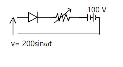
Numerical 7: A battery-charging circuit is shown below in Fig. The forward resistance of the diode can be considered negligible and the reverse resistance infinite. The internal resistance of the battery is negligible. Calculate the necessary value of the variable resistance R so that the battery charging current is 1.0 A.

Numerical 8: A three phase induction motor is wound for four poles and is supplied from a 50 Hz system. Calculate.
i. The synchronous speed;
ii. The speed of the rotor when the slip is 4 per cent;
iii. The motor frequency when the speed of the rotor is 600 r.p.m.
Numerical 9: A 440V shunt motor takes an armature current of 30A at 700 rev/min. The armature resistance is 0.7ohm. If the flux is suddenly reduced by 20 per cent, to what value will the armature current rise momentarily? Assuming unchanged resisting torque to motion, what will be the new steady values of speed and armature current? Sketch graphs showing armature current and speed as functions of time during the transition from initial to final, steady-state conditions.
Numerical 10: Three conductors fitted side by side in the stator of a salient-pole alternator. Each generates maximum voltage of 200V (sinusoidal). The angle subtended at the centre of the stator between adjacent conductors is 20 electrical degrees. If the three conductors are connected in series, find
(i) the r.m.s. value of the effective voltage and
(ii) the ‘breadth factor’. Using the theory that is the basis of this problem, give one reason why three-phase current has been introduced.
Numerical 11: A moving coil ammeter, a thermal ammeter and a rectifier are connected in series with a resistor across a 110 V sinusoidal a.c. supply. The circuit has a resistance of 50Ω to current in one direction and, due to the rectifier, an infinite resistance to current in the reverse direction. Calculate:
(i) The readings on the ammeters; (ii) The form and peak factors of the current wave.
Numerical 12: Three batteries A, B and C have their negative terminals connected together, between the positive terminals of A and B there is a resistor of 0.5 ohm and between B and C three is a resistor of 0.3 ohm,
i. Battery A 105 V, Internal resistance 0.25 ohm’
ii. Battery B 100 V, Internal resistance 0.2 ohm
iii. Battery C 95 V, Internal resistance 0.25 ohm
C. Determine the current values in the two resistors and the power dissipated by them.
Numerical 13: A coil having a resistance of 10 Ohm, and an inductance of 0.15 H is connected in series with a capacitor across a 100V, 50Hz supply. If the current and the voltage are in phase what will be the value of the current in the circuit and the voltage drop across the coil?
Numerical 14: 72 KVA transformer supplies a heating and lighting load of 12 KW at unity power factor and a motor load of 70 kVA at 0.766 (lagging) power factor; Calculate the minimum rating of the power-factor improvement capacitors which must be connected in the circuit the ensure that the transformer does not become overloaded.
Numerical 15: A power of 36 W is to be dissipated in a register connected across the terminals of a battery, having emf of 20V and an internal resistance of 1Ω. Find (i) What value of resistance will satisfy this condition.
(ii) The terminal voltage of the battery for each of the resistances and (iii) The total power expenditure in each case.
Numerical 16: A 3phase, 4pole 24 slot alternator has its armature coils short pitched by one slot. Find the distribution factor and pitch factor.
Numerical 17: A 25 kVa signal phase transformer 2200:200V has a primary and secondary resistance of 1Ω and 0.01
Ω respectively. Find the equivalent secondary resistance and full load efficiency at 0.8pf lagging, if the iron losses of the transformer are 80% of the full load copper losses.
Numerical 18: A 4-pole machine running at 1500 r.p.m. has an armature with 80 slots and 6 conductors per pole.
The flux per pole is 6 x $\displaystyle \mathrm{10^6}$ lines. Determine the terminal e.m.f. of d.c. generator if the coils are lap connected. If the current per conductor is 100 A, determine the electrical power.
Numerical 19: The low-voltage release of an a.c. motor-starter consists of a solenoid into which an iron plunger is drawn against a spring. The resistance of the solenoid is 35 ohm. When connected to a 220 V, 50 Hz, a.c. supply the current taken is at first 2A, and when the plunger is drawn into the “full-in” position the
current falls to 0.7 A. Calculate the inductance of the solenoid for both positions of the plunger, and the
maximum value of flux-linkages in weber-turns for the “full-in” position of the plunger.
Numerical 20: Two 10 MVA 3 phase Alternator operate in parallel to supply at 0.8 power factor with lagging load of 15 MVA. If the output of one Alternator is 8 MVA at 0.9 lagging.
1. Calculate the output of second Alternator.
2. Calculate the value of Power factor of second Alternator.
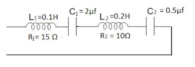
Numerical 21: Find the frequency at which the following circuit resonant

End of document
Comments
Post a Comment