
Piston and Stuffing Box
Pistons.
The piston transmits the gas forces to the Crankshaft through the piston rod. It must have a long fatigue life to survive the fluctuating mechanical and severe thermal stresses during its working life. The material must be resistant to high temperature 'creep, corrosion due to acids and erosion. The material depends on the size, the rating and the fuel used.
Large two stroke engine pistons are made up of various parts - Crown, Skirt and Cooling element. Pistons are cooled either by water (e.g. Sulzer RTA 8-series) or oil (MAN B&W MC engines and Sulzer RTA 2-series).
Water cooled piston
In both the cooling systems, periodic inspection must be carried out. Fresh water cooling has the advantage that fresh water has twice the thermal capacity of oil, and a higher outlet temperature may be maintained (oil gets carbonised at high temperatures). However, water leakage would lead to contamination of the lubricating oil with disastrous consequences.
Material
Cast Steel for piston crowns (for 2 stroke Crosshead engines.)
Aluminium for pistons (for 4 stroke Trunk piston engines.)
Forged steel for piston rod.
Cast iron for piston skirts.
Differences between Two stroke and Four stroke pistons
A Four stroke piston is usually of the trunk type, i.e. it is directly connected to the crankshaft, via connecting rod. It has a Gudgeon pin, which helps in converting the reciprocating motion of the piston to the rotary motion of the crankshaft.
A Two stroke piston is usually of the cross-head type, i.e. it is connected via the piston rod to the Cross-head bearing, which reciprocates along with the piston. The connecting rod connects the crosshead to the crankshaft.
The Four stroke piston is usually shorter in length. It is cast in one piece, and carries compression as well as oil-scraper rings. The piston is usually splash-lubricated, and hence the need for oil scraper rings.
All of the above components are normally of different materials.
In the latest engines, oil cooling is enhanced by the so called Jet shaker principle, which increases the heat transfer rates to improve cooling efficiency.
Piston cleaning ring (PC ring)
a. The development of the new standard of a high top-land and a lower height of the Cylinder liner was, to allow the Cylinder head to bear the brunt of the harsh conditions in the cylinder.
b. This resulted in a lot of carbon formation on the upper part of the Piston crown, which lead to increased wear.
c. The purpose of the Piston cleaning ring is to scrape off excessive ash and carbon formation on the piston top-land and thus prevent contact between the Cylinder liner and these deposits, which would remove part of the cylinder oil from the liner wall.
d. "Bore polish' may be a decisive factor in the deterioration of the cylinder condition, especially for high-rated large engines. PC rings are now standard on the most recent large bore MC engines.
e. The Piston cleaning ring is located on the top edge of the Cylinder liner, just below the Cylinder head.
f. With the increasing mean indicated pressure, the traditional angle-cut ring gap may result in increased thermal load on the cylinder liner.
g. With the new CPR or Controlled Pressure Relief piston ring, the thermal load on the cylinder liner is significantly reduced as no gas will pass through the double lap joint. The top ring is 30 % thicker.
h. The relief grooves ensure an almost even distribution of the thermal load from the combustion gases over the circumference of the liner and, as a consequence, the therma! load on the cylinder liner as well as the second piston ring is reduced. This has been confirmed by temperature measurements.
i. With the CPR piston ring, it is possible to choose the total area of the relief grooves and the optimum number of relief grooves, so as to provide the optimum pressure drop across the whole piston ring pack.
j. A running-in layer of Aluminium Bronze has recently been introduced on the piston rings to facilitate running-in, so no special running-in procedure is now required, thus saving time and costs.
SPWA Wear Trend processing
The Sulzer Integrated Piston Wear Analysis is a means of on-line measurement of piston ring wear. It also gives an advance warning of any piston ring problems, which can then be corrected.
Repairs
Reconditioning of certain engine components such as Piston and grooves is carried out at authorised workshops, where product is identified via reference numbers and at the same time the base metals present. Latest welding materials with correct flux, and proper heat treatment, increase the quality of the reconditioned product.
After welding process, all products must pass a full heat treatment process, which takes at least 24 hours. The actual preheating is steady for 4 hours and it is followed by controlled cooling down. Final machining is done on CNC units,
Reconditioning of piston crowns is done with Inconel welding materials, which can be applied by using submerged-arc strip welding
equipment. Areas around injector bores are protected with Nickel cladding All products are subject to final inspection and Class approval.
Corrosion occurs in the gas duct of the exhaust valve housing around the spindle guide boss and opposite the cooling water inlets. This is caused by the condensation of water which mixes with oxides of sulphur to form sulphuric acid. In order to carry out repairs, welding should be done, if a minimum wall thickness of 5 mm is present.
The corroded area is built-up by special arc welding Diamalloy 1005 coating is applied after grinding down the pertinent area to bare metal. On the exhaust valves of the latest engines, wall thickness has been increased by about 40 % to take care of this.
Recently, a U-type seal has been introduced for the Exhaust valve bottom piece, instead of the o-ring on previous engines. The exhaust valve seat is of the new W-design, where it is claimed that the narrow contact paths will crush possible coke and squeeze it out, so no seat damage occurs. The material is steel and cannot be welded, and it is hardened to a depth of 6- 8 mm.
Stuffing box.
The Stuffing box seals the crankcase from the Scavenge space, in two stroke engines. Shown below is a typical construction for a large marine engine.This shows how the crankcase oil is prevented from getting carried over with the Piston rod during its motion. It also prevents accumulated deposits and excess cylinder oil from entering the Crankcase.
New designs incorporate the following:
a. Additional gas-tight top Scraper package, with a large drain area.
b. Stronger springs.
c. Modified position for the neutral space.
d. Modified channel drains.
e. Ring of Bronze.
f. Hardened piston rods (in way of stuffing box).
g. Two way dismantling (upwards and downwards).
Overhauling
Safety Precautions for overhauling:
Stopped engine
Block the starting mechanism
Shut off starting air supply
Engage turning gear
Shut off cooling water
Shut off fuel oil
Shut off lubricating oil
Lock turbocharger rotors
Data:
Cylinder cover stud, check distance--> 128 - 129 mm
Test pressure --> 7 bar
Piston rod/crosshead, tightening torque --> 430 Nm
Piston rod/crown, tightening torque --> 300 Nm
Piston skirt, tightening torque --> 80 Nm
Cooling oil pipe, tightening torque --> 80 Nm
Piston rod/crosshead, tightening torque + angle --> 100/30 Nm/°
Piston ring new, radial width --> 17.2mm
Piston ring worn, min. radial width --> 14.2mm
Groove No.1 y max. vertical height -->13.2mm
Groove Nos. 2, 3 and 4, max. vertical height --> 10.2mm
Piston top, max. permissible burn-away --> 15mm
Piston ring new, height of ring No. 1 --> 12.4mm
Piston rings new, height of ring Nos. 2, 3 and 4 --> 9.4mm
Minimum free ring gap (before dismantling) --> 28mm
Minimum ring gap, ring No 1 (new ring in new liner) --> 3.4 mm
Minimum ring gap, ring Nos. 2, 3 and 4 (new ring in new liner) -->2.4mm
Vertical clearance, new parts --> 035-0.4 mm.
Vertical clearance, worn parts, max. --> 0.87 mm
Piston complete --> 921 kg
Piston brown --> 200 kg
Piston rod --> 565 kg
Piston skirt --> 57 kg
Piston cooling pipe --> 21kg
Lifting tool, tightening torque --> 150Nm
CPR ring CL groove, min. depth --> 1.1mm
Scavenge port inspection
Checks:
Scvange Port Inspection:-
To detect possible leakages from the piston or cylinder cover, keep the cooling water and cooling oil circulating during the scavenge port inspection.
1. The scavenge port inspection is carried out from the scavenge air receiver. An additional view of the rings is possible through the cleaning cover on the maneouvring side.
Turn the engine at least 1/2 a revolution and start with a unit Arriving downwards, just above the scvange air ports.
Inspect the piston rod and, the lower part of the cylinder wall. While the piston is passing downwards, inspect the piston skirt, all the piston rings, the ringlands and the piston top.

2. Inspect the rings, one at a time, and note down the results.

3. Check the movability and the tension of the piston rings, by pressing against them with a wooden stick.

4. Ring grooves: Measure the total clearance between the piston rings and the ring grooves.
Measurements are to be taken at the top (E) and bottom (F) between the piston ring and piston ring groove.
Total clearance = E + F.

5. Uppermost piston ring: If possible, measure the depth of the pressure relief grooves with a caliper.
The piston rings must be replaced if the radial depth of the grooves has worn down to less than recommended.
The piston rings must be replaced if the radial depth of the grooves has worn down to less than recommended.

Checking of piston rings and piston crown, in connection with piston. overhaul:
6. Remove the piston from the cylinder and place it on the piston support.
Note! It is recommended to replace all the piston rings whenever a piston is removed from the engine.
6. Remove the piston from the cylinder and place it on the piston support.
Note! It is recommended to replace all the piston rings whenever a piston is removed from the engine.

7. Before dismantling the piston rings, measure the free ring gap of all the piston rings.

8. Take off the piston rings by means of the ring expander. Clean and inspect the rings.
9. Measure the radial width of the rings. Note down the results.

10. Clean the ring grooves and check them for burn marks or other deformation.
Measure the ring grooves with a caliper gauge. Clearance in piston ring grooves: The maximum vertical height in a worn ring groove must not exceed the recommended value. The groove is also worn out if there is no chromium layer.
Measure the ring grooves with a caliper gauge. Clearance in piston ring grooves: The maximum vertical height in a worn ring groove must not exceed the recommended value. The groove is also worn out if there is no chromium layer.


11. Clean the piston crown and check the burn-away by means of the template.
Check the burn-away on the whole circumference of the piston crown. Note down the results for later reference.
Check the burn-away on the whole circumference of the piston crown. Note down the results for later reference.

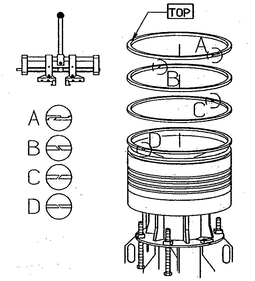
12. Fit the new piston rings (alternately right-hand and left-hand cuts, with the ring gaps staggered 180° and with the TOP mark up-wards), using the ring expander. When mounting the piston rings, use the ring expander to prevent unintended deformation of the rings.

Do not expand the rings more than necessary. The upper ring (CPR-ring) should not be expanded more than to the milled mark on the ring expander.
Dismantling:
1. Turn the crosshead down far enough to give access to the piston rod stuffing box and the screws for the piston rod.
1. Turn the crosshead down far enough to give access to the piston rod stuffing box and the screws for the piston rod.

2. Release the stuffing box by removing the innermost screws from the stuffing box flange.

Note! Do NOT remove the outermost screws from the flange.
3. Remove the screws from the piston rod.
3. Remove the screws from the piston rod.

4. Mount the two distance pieces on the piston rod foot to protect the lower scraper ring and to guide the stuffing box.

5. Dismount the cylinder cover. Carefully smooth out any wear ridges at the top of the cylinder liner.

6. Make a scratch mark in liner and piston cleaning ring to ensure the correct mounting. Remove the piston cleaning ring. Carefully remove any wear ridges at the top of the cylinder liner.

7. Turn the crosshead towards TDC, while checking that the stuffing box lands correctly on the distance pieces.

8. Turn to TDC.
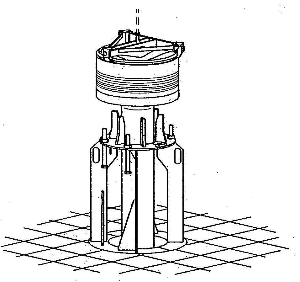
The top of the piston is now free of the cylinder liner. Clean the lifting groove of the piston crown and mount the lifting, tool in such a manner that the two 'fixed' claws of the tool fit into the lifting groove of the piston.
Fit the third, adjustable, claw of the tool to the lifting groove and tighten it up against the stop of the toot. Lift the piston out of the cylinder liner.

9. If the lifting height is limited, it can be necessary to guide the piston rod foot in between the cylinder cover studs.
Note! Alternatively, with low lifting height, remove one of the cylinder cover studs with the stud setter.
Note! Alternatively, with low lifting height, remove one of the cylinder cover studs with the stud setter.

10. Lower the piston rod foot and stuffing box through the opening in the platform. Place the two halves of the support around the piston rod and secure the two halves with screws.

11. Place a cover over the opening for the piston rod stuffing box in the bottom of the cylinder unit. clean measure and recondition the cylinder liner.

12. Turn the crosshead down far enough to permit mounting of the protective rubber cover on the crosshead bearing cap.
The protective rubber cover should remain in place to protect the crosshead bearing journal from impurities until the piston is re-mounted.
13. If the space conditions above the engine make it impossible to remove the piston in the normal way, the piston can be removed as follows: Remove one or two cylinder cover studs, using the stud setter.
Lift the piston high enough to give ample room over the cylinder cover studs. Place the supporting tools on the cylinder cover studs.

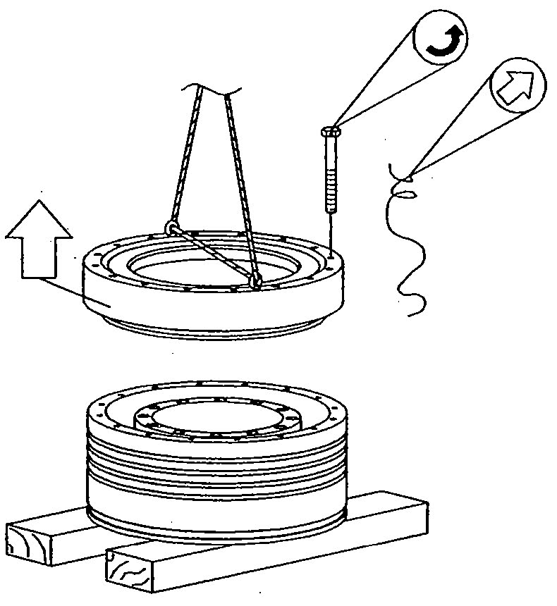
14. Place the collar ring on the supporting tools and mount the clamp on the collar ring. Check that the distance pieces have con-tact with the piston. Remove the lifting tool from the piston. Hook the crossbar on to the crane and at-tach the collar ring to the crossbar.

15. Lift the piston to the maximum crane height. Run the crane athwartship and, at the same time, tilt the piston.
Note! Tilting of the piston must only take place with the piston rod stuffing box mounted on the piston rod. Keep the piston rod clear of the cylinder liner and studs while carrying out the tilting.
When space conditions permit, straighten up the piston and lead it over to the cut-out in the platform for overhauling the piston.
When the piston is at a suitable height above the platform cut-out, position the piston support around the piston rod and clamp.
Now lower the piston while guiding the sup-port to the platform cut-out.
After landing the piston and ensuring that it rests correctly on the support, remove the tilting tool.

Note! On engines with extremely low lifting height, use the engine room double-jib crane instead of the transverse piece.
Overhauling:
1. Ease the piston down so that the stuffing box is below the floor.
1. Ease the piston down so that the stuffing box is below the floor.

2. Assemble the two halves of the piston sup-port around the piston rod and land the pis-ton on the support. Check and remove the piston rings.
3. Dismount the locking wire and the innermost screws between the rod and the piston crown.

4. Dismount the locking wire and screw up the support screws of the piston support to a position just below the piston skirt.
Remove the piston skirt screws.

5. Screw the four screws of the support downwards until the skirt rests on the support. If the skirt wilt not budge, free it by means of two dismantling screws. Lift away the piston crown. Remove and discard the sealing rings on the piston rod and on the skirt.

6. Dismount the bolts of the cooling oil pipe flange. Mount the eye bolts and lift out the cooling oil pipe. After inspection of the cooling oil pipe, re-mount the pipe.

Alternatively, the piston can be dismantled in the following way:
7. With the piston standing in the piston support tool, remove the piston rod stuffing box.

8. Lift the piston with the lifting tool. Land the piston rod foot on a wooden-plank.
Note! During the lift, follow with the crane to keep the crane positioned vertically above the lifting point. Lower the piston crown to the platform and land it on a wooden plank, so that it is possible to remove the lifting tool.
Note! During the lift, follow with the crane to keep the crane positioned vertically above the lifting point. Lower the piston crown to the platform and land it on a wooden plank, so that it is possible to remove the lifting tool.

9. Remove the lifting tool from the piston crown. Attach the lifting bracket to the bot-tom of the piston rod foot. Hook the crane on to the lifting bracket.

10. Lift the piston rod foot clear of the wooden plank. Keep lifting until the piston rod is in a vertical position.

11. Place the piston in an upright position with the piston crown resting on wooden-blocks.
Dismount the locking wire and the inner-most screws between the rod and the pis-ton crown. Lift the piston rod away and land it in a horizontal position on a couple of wooden planks.

12. Remove the locking wire and the screws in the skirt and mount two eye bolts in the holes intended for dismantling screws. Lift the skirt and land it on a couple of planks.
13. Thoroughly clean and inspect all parts of the piston. Regarding check of the piston crown.
Replace all sealing rings of the piston, All the new sealing rings must be coated with lubricating oil before the piston is assembled. Coat all screws with Molybdenum Disulphide (MoS2). Assemble the piston in the reverse order to disassembly. Use the guide screw to ensure the correct positioning of the piston rod in relation to the piston crown.

Tighten all the screws diagonally to the torque recommended.
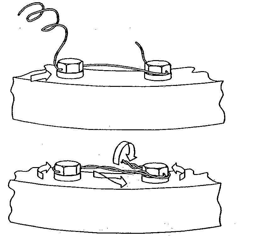
14. Lock all the screws with locking wire. Mount the locking wire in such a way that the wire is tightened if one of the screws works loose.
14. Lock all the screws with locking wire. Mount the locking wire in such a way that the wire is tightened if one of the screws works loose.
15. Fill the piston and piston rod with lubricating oil. Mount the pressure-testing tool around the base of the piston rod.

Pressure-test the piston at the pressure stated on the data sheet. Check the contact surfaces of the piston and the sealing rings for tightness. Check that there are no cracks in the piston crown,
Mounting:
1. Check the piston rings and piston crown as described above, Coat the piston rings, piston rod and cylinder liner with lubricating oil.
2. Mount the lifting tool on the piston crown.
1. Check the piston rings and piston crown as described above, Coat the piston rings, piston rod and cylinder liner with lubricating oil.
2. Mount the lifting tool on the piston crown.

3. Ensure that the stuffing box is correctly positioned over the guide pins in the distance pieces mounted on the piston rod foot. Coat the O-rings of the stuffing box with oil.
4. Remove the protective rubber cover from the crosshead.

5. Remove the cover from the piston rod stuffing box opening in the bottom of the cylinder unit.
6. Turn the crosshead to a position 45° from TDC. Mount the guide ring for piston rings on the cylinder liner.

7. Lower the piston into the cylinder liner while guiding the piston rod foot through the cut-out in the stuffing box flange until the piston rings are inside the liner.

8. Turn the crosshead nearly to TDC while checking that the guide ring of the crosshead enters the centre hole in the piston rod.

9. After turning the crosshead fully to TDC, and ensuring that the piston rod has full contact with the crosshead, unscrew the adjustable claw of the lifting tool and pull the lifting tool free of the lifting groove in the piston. Remove the lifting tool and the guide ring for piston rings.

10. Turn down and land the stuffing box on the stuffing box flange. Check that the holes in the stuffing box and stuffing box flange are correctly centred. Remove the distance pieces from the piston rod foot.

11. Tighten down the piston rod stuffing box by means of the screws, through the inner holes in the stuffing box flange.

12. Mount and tighten the piston rod screws. Tighten the screws to the specified torque and lock with locking wire.

13. Mount the piston cleaning ring according to the scratch mark. If the PC-ring is damaged (broken or cracked), it must be replaced by another ring.

14. If the cylinder cover studs have been re-moved, remount them. Carefully clean the, surfaces around the base of the studs and check the O-rings on the studs. Mount the cylinder cover studs with the stud setter. Screw the stud down to contact and one half revolution back.

15. Land the cylinder cover on the liner and check the distance the stud is protruding from the cylinder cover. If necessary, adjust the distance 'D' by turning the stud.

16. Tighten the cylinder cover and mount the necessary pipes. Smear the piston rod with molybdenum di-sulphide, and turn the crankshaft a couple of revolutions. Start the engine and keep it running for about 15 minutes at a number of revolutions corresponding to very slow. Then stop the engine and inspect the piston rod and stuffing box.
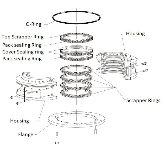
Stuffing Box.
It is a seal between the scvange spaces and the crankcase in the area of piston rod penetration. It seals the crankcase oil entering into the scvange space, and scavange deposits or cylinder oil entering the crankcase. It is made of two sections. Each section consists of segmented mental rings held aginst the poston rod by garter springs.
Materials:
Housing - cast iron or cast steel.
Rings- Cast iron or brass or bronze or PTFE.
Lamellas - Cast iron or carbon.

Stuffing Box Problems:
(a) Poor sealing caused by worn out rings, badly aligned ring joints, sticky rings, closed butt joints, weak springs, excessive axial clearance or scoring/wearing of the piston rod.
(b) Consequences of stuffing box not performing properly is a loss of crankcase oil, higher cost, contamination of crankcase with scvange deposits and unburnt cylinder oil.
(c) Indications of poor stuffing box gland sealing:
-Crankcase oil contamination test giving poor results,
- A case of no oil replenishment,
-Increasing TBN or viscosity,
-Reduced piston cooling effect,
-Poor lubrication.
.

.
Safety Precautions for Overhauling:
Stopped engine
Block the starting mechanism
Shut off starting air supply
Engage turning gear
Shut off cooling water
Shut off fuel oil
Shut off lubricating oil
Lock turbocharger rotors
Data:
Stuffing box flange, outer screws tightening torque--> 80 Nm
Stuffing box flange, inner screws tightening torque--> 80 Nm
Stuffing box halves, tightening torque -->80 Nm
Uppermost rings, ring-end clearance -->4x6 mm
Lowermost rings, ring-end clearance -->3x3 mm
Check length for the six uppermost springs:
—FO=ON...... L0 = 639 mm
— F 1 = 153 +/— 7 N L 1 = 763 mm
— F 2 = 163 +/— 10 N L 2 = 835 mm
Check length for the four lowermost springs:
—FO = ON...... L0 = 496 mm
—F 1 = 150 +/— 7 N L1 = 646 mm
—F 2=200 +/-10 N L2 = 714 mm
Stuffing box complete -->63 kg
Stuffing box half --> 19 kg
.
Tools for overhauling:

Checking:
1. After the piston rod stuffing box has been dismantled, check the following clearances:
Uppermost scraper ring and sealing rings
a. Clearance at ring ends (scraper ring).
b. Total clearance (scraper ring).
c. Clearance at ring ends (sealing rings).
d. Total clearance (sealing rings).
Lowermost scraper rings
a. Clearance at ring ends.
b. Total clearance.
Uppermost scraper ring and sealing rings
a. Clearance at ring ends (scraper ring).
b. Total clearance (scraper ring).
c. Clearance at ring ends (sealing rings).
d. Total clearance (sealing rings).
Lowermost scraper rings
a. Clearance at ring ends.
b. Total clearance.

As a general guide, it is recommended depending on the overhauling intervals and one's own experience to replace sealing rings and scraper rings when the specified clearance values have been halved.
2. Check the length of the springs at different loads. Adjust the loads to achieve the lengths stated in Data.
If the loads necessary are outside the limits stated in Data, the springs must be discarded.

It is recommended to renew the springs for the sealing rings when the rings are renewed.
Dismantling:
In connection with dismantling of the piston, only the innermost screws in the stuffing box flange should be removed.
If, in the period between piston overhauls, it becomes necessary to inspect the piston rod stuffing box, proceed as follows:
1. Turn the crosshead to about 90° from TDC.
Mount the rubber cover around the piston rod to protect the crosshead bearing from impurities.
2. Remove the drain oil pipe and all innermost screws and all outer screws except for two screws placed diametrically opposite in the stuffing box flange; longitudinally to the engine.
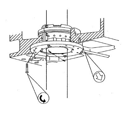
3. Mount the worktable around the piston rod so that the two remaining screws in the stuffing box flange can be loosened through the holes.

4. Remove the two long dismantling screws from the worktable. Mount them in the stuffing box through the holes in the worktable. Remove the remaining two screws from the stuffing box.

5. Turn the piston to BDC, thereby withdrawing the stuffing box from the cylinder frame bottom.

6. Remove the two long dismantling screws from the stuffing box and mount them in the worktable.
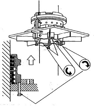
By means of the four short screws in the worktable, press the stuffing box out of the flange.
Overhauling:
Normally, overhaul of the piston rod stuffing box is carried out by routine methods in connection with the dismantling (pulling) of the pistons. During such overhauls, the piston rests on a support placed over one of the cut-outs in the top platform.
Work on the stuffing box is then carried out from the platform below.
Overhaul inside the engine is carried out in the same way as outside the engine.
1. Mount two eye bolts in the stuffing box flange, and hook on two tackles.
Lift the stuffing box a little up the piston rod, and mount the worktable round the piston rod at a suitable working height.

2. Remove the O-ring of the stuffing box. If the O-ring is intact and is to be used again, move it up the piston rod and secure it in this position, for example with tape.

Remove the nuts from the stuffing box assembling bolts.
3. Take out the six bolts, and pull away one stuffing box half. Mount two eye bolts on the stuffing box half and remove it from the worktable.

4. Using a feeler gauge, measure the vertical clearance of the rings.
5. Remove the remaining stuffing box half and press all sealing rings and scraper rings down against the worktable.
6. Measure the clearance between the ring segments to determine whether replacement is necessary. Dismantle and stack the rings in the same order as when fitted in the stuffing box. Carefully clean all the ring segments. Inspect and assess the surface quality of the sealing rings. If their sliding surfaces have scratches or marks, replace the rings.
7. Check the lengths of the springs.
8. Inspect the surface of the piston rod. If small longitudinal scratches have occurred (caused by poorly adapted stuffing box rings), smooth the piston rod surface care-fully with a fine grained carborundum stone.

9. Clean the halves of the stuffing box housing.
10. Lubricate the piston rod (in the area where all the ring units in the stuffing box-will be positioned) with molybdenum disulphide (MoS2).

• Place the lowermost scraper ring segments on the worktable.
• Place the spring round the segments, and hook the spring ends together.
Repeat this procedure for the remaining scraper rings.
On top of the scraper rings, assemble the two sealing ring units (each consisting of a 4-part and an 8-part ring).
Assemble the 8-part sealing ring so that the two guide pins face upwards, place the spring round the segments and, hook the spring ends together.
Assemble the 4-part sealing ring above the 8-part sealing ring. Push the two rings together in such a manner that the guide pins in the lower sealing ring engage with the two holes in the upper sealing ring. Finally, assemble the uppermost ring unit (consisting of a 4-part scraper ring and an 8-part sealing ring).
11. Use the stuffing box half on the worktable to adjust the height of all the assembled ring units on the piston rod until the ring units are opposite the corresponding grooves in the stuffing box housing. Subsequently, push the stuffing box half into con-tact with the piston rod, round the ring units.

Note! If the stuffing box is assembled inside the engine, place two pieces of plywood of the same thickness as the flange on the worktable, to ease the assembling.
12. Check the ring clearance again.
Then place the other half of the stuffing box housing on the worktable, pushing it into place round the rings.
Then place the other half of the stuffing box housing on the worktable, pushing it into place round the rings.

Mount and tighten up the fitted bolts to the torque specified. Mount the O-ring in the stuffing box groove.
13. Mount eye bolts and wire ropes, and lift the stuffing box a little.

Remove the worktable and lower the stuffing box until it rests against the distance pieces on the piston rod foot. Remove wire ropes and screws.
Mounting:
1. In connection with mounting of the piston, only the innermost flange screws are to be mounted and tightened.
1. In connection with mounting of the piston, only the innermost flange screws are to be mounted and tightened.

After overhauling the stuffing box inside the engine, assemble the stuffing box halves on top of the four screws. Mount the two long screws from the worktable in the stuffing box. Turn down the short screws so that the stuffing box lands on the flange.
2. Turn the piston upwards until the stuffing box is in place in the cylinder frame.

Note! Make sure that the two guide pins in the flange enter the guide holes in the bottom of the cylinder frame.
3. Mount two screws in the flange through the holes in the worktable.

4. Remove the long screws from the stuffing box and mount them in the worktable.

Remove the worktable from the piston rod.
5. Mount and tighten all the inner and outer screws for the stuffing box.

6. Remove the protecting rubber cover from the piston rod/crosshead. Smear the piston rod with molybdenum disulphide. Then turn the crankshaft a couple of revolutions.
Start up the engine and keep it running for about fifteen minutes at a number of revolutions corresponding to very slow or idle speed.
Then stop the engine and inspect the piston rod and stuffing box.
Comments
Post a Comment