
Cylinder Liners of marine diesel engine
<<Engine construction and Operation
Causes of liner wear
A. Corrosion
i. Sulphuric acid.
ii. Hydrochloric acid.
B. Abrasion.
i. Micro-Seizure.
ii. Scratches.
Cloverleafing is a term used to describe the corrosive wear at points around the liner circumference, which are in between the lubricating oil entry points. The cylinder oil being alkaline neutralises acids in the vicinity of the oil entry points. This leads to the Cloverleaf type wear.
The lubricating oil grooves in the cylinder liner should be shaped and sloped such that, the combustion gas pressure forces the lubricant away from the quill, to assist in the even distribution of the lubricant. The groove should not end in the lubricating hole, but at a point slightly below it.
Abrasive wear.
Corrosive wear.
Abrasive wear
This occurs when abrasive particles enter the combustion space with scavenging air or as a result of poor quality or contaminated fuel. Instances of extremely high abrasive wear rates have occurred in the past due to the burning of fuel heavily contaminated by catalytic fines.
Corrosive wear
This is the more common cause of cylinder liner wear, caused when burning heavy fuel which contains significant amounts of sulphur. As the fuel burns the sulphur combines with oxygen to produce oxides of sulphur which form sulfuric acid in contact with water. To minimise the formation of acids it is important that cylinder liner temperatures are maintained above the dew-point.
To minimise cylinder liner wear it is imperative that ship’s engineers operate the engine correctly. This includes the Correct quantity and grade of cylinder lubrication.
Correctly fitted piston rings.
Correct warming through prior to starting.
Well maintained and timed fuel injectors.
Well managed fuel storage and purification plant.
Correct cooling water and lubricating oil temperatures.
Correct scavenge air temperatures.
Engine load changes are carried out gradually.
Well maintained equipment.
The deterioration of fuel quality that has taken place years coupled with the increased pressures and temperatures that occur during the combustion process has resulted in liners and piston rings operating under very severe conditions. Despite these adverse operating conditions cylinder liner wear rates have been reduced in recent years with large 2-stroke manufacturers claiming 0-03 mm/1000 hrs and medium speed 4-stroke engine manufacturers claiming wear rates of 0-02 mm/1000 hrs when operating on heavy fuel.
These wear rates have been achieved as a result of a number of factors such as:
The development of highly alkaline lubricating oils to neutralise the acids formed during combustion.
The development of load-dependent temperature control of cooling water which maintains the cylinder liner temperature at optimum level.
The use of good quality cast iron with sufficient hard phase content for cylinder liners.
Careful design of piston ring profiles to maximise lubricating oil film thickness,
Improvements in lubricating oil distribution across cylinder liner surface. This includes multi-level injection in 2-strokes engines and forced piston skirt lubrication in 4-stroke engines.
Improved separation of condensate from scavenging air.
Cylinder liner wear profile
The figure shows the wear profile of both a 4-stroke and 2-stroke engine cylinder liner.
Cylinder Liner Cooling arrangement and wear down.
The cylinder liner is inserted into the Cylinder block from above and retained by the Cylinder head. They are water-cooled and have bore cooling in way of the piston running surface. The main problem of corrosion has been tackled in the new RTA 84 T by having two bands of Teflon insulation enclosed within sheet steel (Haramaki). The wear rate of the Cylinder liner has now been reduced to less than 0.1 mm / 1000 hrs. The load-controlled cooling system has ensured that the temperature of the liner is above the dew point, and has thus significantly reduced the problems due to corrosion. Life of the Liner is now increased to about 10 years, which has reduced maintenance costs. At the time of Overhaul of the unit, liners are cleaned, inspected and calibrated. They must be free from scoring, cracks and ridges. If the liner is chrome plated, the worn-off portion must be carefully examined. The corresponding part of the Piston must be examined for gas blow-past. Cracked or Scored liner must be replaced. If the chrome plating is showing signs of wear, the liner needs to be re-plated. The Liner must be inspected at the removal of the piston (during annual surveys) or in case of seizure. The maximum wear of the Liner is around 0.6 to 0.8 % of the bore, which is the thumb rule for replacement. The readings should be carried out using the template, in both Fore-Aft and Port-Starboard directions.Causes of liner wear
A. Corrosion
i. Sulphuric acid.
ii. Hydrochloric acid.
B. Abrasion.
i. Micro-Seizure.
ii. Scratches.
Cloverleafing is a term used to describe the corrosive wear at points around the liner circumference, which are in between the lubricating oil entry points. The cylinder oil being alkaline neutralises acids in the vicinity of the oil entry points. This leads to the Cloverleaf type wear.
The lubricating oil grooves in the cylinder liner should be shaped and sloped such that, the combustion gas pressure forces the lubricant away from the quill, to assist in the even distribution of the lubricant. The groove should not end in the lubricating hole, but at a point slightly below it.
Cylinder Liner Wear
Cylinder liner wear can be divided into:Abrasive wear.
Corrosive wear.
Abrasive wear
This occurs when abrasive particles enter the combustion space with scavenging air or as a result of poor quality or contaminated fuel. Instances of extremely high abrasive wear rates have occurred in the past due to the burning of fuel heavily contaminated by catalytic fines.
Corrosive wear
This is the more common cause of cylinder liner wear, caused when burning heavy fuel which contains significant amounts of sulphur. As the fuel burns the sulphur combines with oxygen to produce oxides of sulphur which form sulfuric acid in contact with water. To minimise the formation of acids it is important that cylinder liner temperatures are maintained above the dew-point.
To minimise cylinder liner wear it is imperative that ship’s engineers operate the engine correctly. This includes the Correct quantity and grade of cylinder lubrication.
Correctly fitted piston rings.
Correct warming through prior to starting.
Well maintained and timed fuel injectors.
Well managed fuel storage and purification plant.
Correct cooling water and lubricating oil temperatures.
Correct scavenge air temperatures.
Engine load changes are carried out gradually.
Well maintained equipment.
The deterioration of fuel quality that has taken place years coupled with the increased pressures and temperatures that occur during the combustion process has resulted in liners and piston rings operating under very severe conditions. Despite these adverse operating conditions cylinder liner wear rates have been reduced in recent years with large 2-stroke manufacturers claiming 0-03 mm/1000 hrs and medium speed 4-stroke engine manufacturers claiming wear rates of 0-02 mm/1000 hrs when operating on heavy fuel.
These wear rates have been achieved as a result of a number of factors such as:
The development of highly alkaline lubricating oils to neutralise the acids formed during combustion.
The development of load-dependent temperature control of cooling water which maintains the cylinder liner temperature at optimum level.
The use of good quality cast iron with sufficient hard phase content for cylinder liners.
Careful design of piston ring profiles to maximise lubricating oil film thickness,
Improvements in lubricating oil distribution across cylinder liner surface. This includes multi-level injection in 2-strokes engines and forced piston skirt lubrication in 4-stroke engines.
Improved separation of condensate from scavenging air.
Cylinder liner wear profile
The figure shows the wear profile of both a 4-stroke and 2-stroke engine cylinder liner.
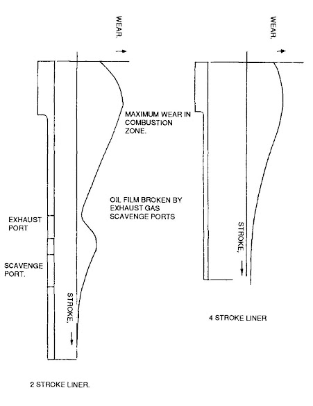
The high temperatures and pressures that occur at this point.
Because the piston reverses direction at this point
Hydrodynamic lubrication is not established.
Acids formed during combustion attack the liner material.
Cloverleafing
Despite the close control of cylinder surface temperatures, acids are still formed which must be neutralised by the cylinder lubricating oil. This requires that the correct quantity and TBN grade of oil is injected into the cylinder. Immediately the oil enters the cylinder it will start neutralising the acids, becoming less alkaline as it does so. If the TBN of the oil is too low then its alkalinity may be depleted before it has completely covered the liner surface. Further contact with the acids may lead to the oil itself becoming acidic. This will lead to the phenomenon is known as “cloverleafing” in which high corrosive wear occurs on the liner between the oil injection points Severe cloverleafing can result in gas blow-by past the piston rings and ultimate failure of the liner.
Micro-seizure
This is due to irregularities in the liner and piston rings coming into contact during operation as a result of a breakdown of lubrication due to an insufficient quantity of lubricating oil, insufficient viscosity or excessive loading. This results instantaneous seizure and tearing taking place. In appearance micro-seizure resembles abrasive wear since the characteristic marks run axially on the liner. Micro-seizure may not always be destructive, indeed it often occurs during a running-in period. It becomes destructive if is persistent and as a result of inadequate lubriation.
Removal of cylinder liner
The Cylinder liner may be removed in case of any defect/damage. The following needs to be carried out
a. Drain the jacket water and remove the cylinder head.
b. Engage the Turning Gear and turn the unit to BDC. Grind away any ridges on the top of the Liner.
c. Remove the Piston.
d. Disconnect Lubricator fittings and remove.
e. Fit the lifting, tool.
f. Lift the liner completely by means of the engine room Crane.
g. Land the liner on suitable planks, to carry out inspection.
h. While re-fitting, ensure calibration is done.
i. New sealing rings are fitted, suitably coated with molybdenum disulphide.
j. In the case of a new Liner, new Piston rings must be used.
k. All running-in procedures to be carried out as per maker's instructions.
Removal:-
safety precautions:-
- stop the engine.
- inform wheelhouse.
- block the starting air mechanism.
- shut off the air supply.
- engage turning gear.
- shut off cooling water.
- shut off fuel oil.
- shut off lube oil.
1. Dismount the cylinder cover. Discard the sealing ring from the top of liner. Turn the piston down far enough to make it possible to remove the wear ridges at the top of the liner. Dismount the piston and piston cleaning ring. mount the two lifting screws in the cylinder liner. check with a feeler gauge that there is no clearance between the liner and lifting screw.

2. Disconnect the cylinder lubrication connections. Dismount cooling water pipes between cooling jacket and cylinder cover.
3. Attach the crane to the lifting tool. Hook the chains from the lifting crossbar onto the lifting screws and lift the cylinder liner with the cooling jacket out of the cylinder frame. Land the cylinder liner vertically on, for instance, a couple of planks. Clean the cylinder frame internally, paying special attention to the contact surfaces for the cylinder liner at the top of the cylinder frame. Discard the O-rings on the cooling water pipes. Clean the pipes carefully.
Fitting back:-
1. Loosen the water connections on the cooling jacket. Mount the two lifting screws in the cylinder liner. Hook the chains from the lifting crossbar onto the lifting screws, and lift the jacket/liner assembly. Mount the lowermost O-ring and apply a little lubricating oil on the ring.
2. Check that the joint surfaces on the cylinder frame and cylinder liner are completely clean. Coat the joint surfaces with permatex or a similar liquid sealing compound. Mount the cylinder liner in the cylinder frame. Replace the O-rings on the water connections and mount the water connections on the cooling jacket. If one or more cylinder cover studs have been removed during the dismantling of the cylinder cover, remount the studs using the stud setter and a torque wrench.
3. Fit a new gasket between the cooling water inlet pipe and the cooling jacket. Mount and tighten the screws.
4. Mount the non-return valves for cylinder lubrication in the bores of the liner.
Screw the pipes from the lubricator onto the non-return valves, but do not tighten.
Vent the cylinder lubricating system by manually pumping each individual pipe through until oil, without air bubbles, comes out from the union pipe/non-return valve. When this is in order, tighten the pipes firmly on the non-return valves and again pump manually until it is certain that each individual lubricating point functions correctly. 5. Lubricate the inside of the cylinder liner with cylinder lubricating oil and mount the piston.
6. Mount the sealing ring and the cylinder cover. Tighten the upper water connections on the cooling jacket as soon as the cylinder cover is correctly positioned.
C. State the important checks to be made on the engine before after fitting.
(1)The new spare cylinder liner IS removed safely from its stowed position and made to rest on wooden packings in a vertical position to enable proper cleaning and removal of the protective coating from the liner inner surface. The liner is to be gauged at the usual locations in fwd—aft and P—S directions using the calibration template.
(2) The internal space in the entablature, especially the cooling water space around the liner to be thoroughly cleaned, by removing the accumulated sludge and descaled thoroughly, and the space painted using a recommended anti-corrosive coating. Particular attention is to be paid to the location of the rubber rings, which should be descaled thoroughly.
(3)The liner is now to be lifted and inserted into the jacket(entablature) and made to rest on its flange seat on the entablature. When inserting the liner it should be made to coincide with the markings or locating dowel/s. After the liner rests on the entablature, the following checks must be made from the scavenge space:-
* the cylinder lubrication quill holes coincide correctly.
*The scavenge ports coincide with corresponding ports in the entablature. (where such design features exist).
* The height from the end of the liner to the diaphragm surface is the same throughout. This should be checked with a steel flat scale. This confirms that the liner is sitting squarely.
(4)The liner is removed and laid in its previous location. The rubber sealing rings are fitted ensuring they are not twisted. To ensure they are not twisted, the mould line on the rings must be exposed, the rings stretched while lifting them and released at the groove location. The Garlock square cord is to be lightly caulked in its groove. This cord is usually placed above the rubber rings.
The rings are to be smeared with soft soap for easy entry.
(5)The liner is lifted placed correctly on the entablature after checking the dowel marks and then forced in using the cylinder head or any device provided for this purpose(depending on the design of the engine). An inspection must be made from the scavenge space to confirm that the liner is fitted and seated as per the original seating when fitted without the rubber rings.
Checks:- (1) cooling water tightness check:- The jacket outlet is to be blocked, the jacket space filled with fresh water and the space subjected to a pressure of 2 kg/sq cm, using a hand hydraulic pump. The pressure was to be maintained for 30 minutes and during this time the scavenge space was examined for signs of leakage from the fitted liner.
(2) The liner is to be gauged in all locations using the micrometre and template. This is to ensure that the liner bore has not been strained. This can happen if the liner dimensions are not correct.
In such a situation the liner should not be used and the old liner is to be refitted.
(3) The piston with the piston rod is to be inserted without the rings and tightened on the crosshead. The crank is made to rotate and the clearance between the piston and liner bore measured using a long feeler gauge in 4 locations ie fwd, aft, P and S should not exceed 1mm. this measurement is taken at TDC, MID TRAVEL POSITION and BDC This check assures that the vertical alignment is in order.
The unit is now ready to be assembled with the running gear and made ready for sailing.
Pressure testing of cylinder head:- The dismantled cylinder head is pressure tested using a hydraulic hand water pump. The inlet side of the head from jacket discharge is fitted with a suitable nipple connected to the hydraulic pump, and the discharge side is blanked with a purging cock to remove air. The hand pump is pumped with slow strokes till the pressure is twice the normal working pressure of the water. The pump is fitted with a calibrated gauge to record the pressure. The pressure is held for 30 minutes and the head is checked for any cracks especially on the firing side.
Various methods are used to supply lubricating oil to the cylinder walls. In Trunk piston engines with forced. bearing lubrication, the quantity of oil thrown from the bearings onto the cylinder walls is sufficient to lubricate the liner/ piston rings. Scraper rings are provided to prevent excessive consumption of the crankcase oil. In two-stroke engines, the supply of cylinder lubricant is achieved through forced feed lubricators, using a different oil than that used in the crankcase.
The oil is injected into each unit through Quills, which are basically non-return valves. These eliminate the pressure pulsations in the lubricator delivery pipe and prevent air products of combustion from entering. They also keep the pipe full, when the engine- is stationary.
Modern Sulzer engines use multi-level lubrication. The lubricator pumps are driven by frequency-controlled electric motors, using load-dependant lubrication. The oil is distributed to oil accumulators by oil distributors. The cylinder oil feed rate should be sufficient to ensure a clean and wet liner, without excessive accumulation of lubricating oil. A rough rule of thumb is 0.6 gm/ BHP-hr. This feed rate should be adjusted in accordance With the actual load so that it is proportional to the mean effective pressure. The feed rate per cylinder per 24 hrs should never be allowed to drop below 40% of the recommended oil consumption.
The principal objects of cylinder lubrication are:
1. To separate sliding surfaces with an unbroken oil film.
2. To form an effective seal between piston rings and cylinder liner surface to prevent blow past of gases.
3. To neutralise corrosive combustion products and thus protect cylinder liner, piston and rings from corrosive attack.
4. To soften deposits and thus prevent wear due to abrasion.
5. To remove deposits to prevent seizure of piston rings and keep the engine clean.
6. To cool hot surfaces without burning.
In practice, some oil burning will take place, if excessive this would be indicated by blue smoke and increased oil consumption.
As the oil burns, it should leave as little and as soft a deposit as possible. Over lubrication should be avoided.
When the engine is new, cylinder lubrication rate should normally be greater than when the engine is run in. Reasons for this increased lubrication are:
(1) surface asperities will, due to high local temperatures, cause increased oxidation of the oil and reduce its lubrication properties,
(2) sealing of the rough surfaces is more difficult,
(3) worn off metal needs to be washed away.
The actual amount of lubricating oil to be delivered into a cylinder per unit time depends upon stroke, bore and speed of an engine, engine load, cylinder temperature, type of engine, the position of cylinder lubricators and type of fuel being burnt.
Position of the cylinder lubricators for injection of oil has always been a topic of discussion, the following points are of importance:
1. They must not be situated too near the ports, oil can be scraped over the edge of ports and blown away.
2. They should not be situated too near the high-temperature zone or the oil will burn easily.
3. There must be sufficient points to ensure as even and as complete a coverage as possible.
Ideally, timed injection of lubricant delivering the correct measured quantity to a specific surface area at the correct time in the cycle is the aim, but is difficult to achieve in practice.
Latest Developments
Because the piston reverses direction at this point
Hydrodynamic lubrication is not established.
Acids formed during combustion attack the liner material.
Cloverleafing
Despite the close control of cylinder surface temperatures, acids are still formed which must be neutralised by the cylinder lubricating oil. This requires that the correct quantity and TBN grade of oil is injected into the cylinder. Immediately the oil enters the cylinder it will start neutralising the acids, becoming less alkaline as it does so. If the TBN of the oil is too low then its alkalinity may be depleted before it has completely covered the liner surface. Further contact with the acids may lead to the oil itself becoming acidic. This will lead to the phenomenon is known as “cloverleafing” in which high corrosive wear occurs on the liner between the oil injection points Severe cloverleafing can result in gas blow-by past the piston rings and ultimate failure of the liner.
Micro-seizure
This is due to irregularities in the liner and piston rings coming into contact during operation as a result of a breakdown of lubrication due to an insufficient quantity of lubricating oil, insufficient viscosity or excessive loading. This results instantaneous seizure and tearing taking place. In appearance micro-seizure resembles abrasive wear since the characteristic marks run axially on the liner. Micro-seizure may not always be destructive, indeed it often occurs during a running-in period. It becomes destructive if is persistent and as a result of inadequate lubriation.
Cylinder Liner Overhauling.
Removal of cylinder liner
The Cylinder liner may be removed in case of any defect/damage. The following needs to be carried out
a. Drain the jacket water and remove the cylinder head.
b. Engage the Turning Gear and turn the unit to BDC. Grind away any ridges on the top of the Liner.
c. Remove the Piston.
d. Disconnect Lubricator fittings and remove.
e. Fit the lifting, tool.
f. Lift the liner completely by means of the engine room Crane.
g. Land the liner on suitable planks, to carry out inspection.
h. While re-fitting, ensure calibration is done.
i. New sealing rings are fitted, suitably coated with molybdenum disulphide.
j. In the case of a new Liner, new Piston rings must be used.
k. All running-in procedures to be carried out as per maker's instructions.
Removal:-
safety precautions:-
- stop the engine.
- inform wheelhouse.
- block the starting air mechanism.
- shut off the air supply.
- engage turning gear.
- shut off cooling water.
- shut off fuel oil.
- shut off lube oil.
1. Dismount the cylinder cover. Discard the sealing ring from the top of liner. Turn the piston down far enough to make it possible to remove the wear ridges at the top of the liner. Dismount the piston and piston cleaning ring. mount the two lifting screws in the cylinder liner. check with a feeler gauge that there is no clearance between the liner and lifting screw.
2. Disconnect the cylinder lubrication connections. Dismount cooling water pipes between cooling jacket and cylinder cover.
3. Attach the crane to the lifting tool. Hook the chains from the lifting crossbar onto the lifting screws and lift the cylinder liner with the cooling jacket out of the cylinder frame. Land the cylinder liner vertically on, for instance, a couple of planks. Clean the cylinder frame internally, paying special attention to the contact surfaces for the cylinder liner at the top of the cylinder frame. Discard the O-rings on the cooling water pipes. Clean the pipes carefully.
Fitting back:-
1. Loosen the water connections on the cooling jacket. Mount the two lifting screws in the cylinder liner. Hook the chains from the lifting crossbar onto the lifting screws, and lift the jacket/liner assembly. Mount the lowermost O-ring and apply a little lubricating oil on the ring.
2. Check that the joint surfaces on the cylinder frame and cylinder liner are completely clean. Coat the joint surfaces with permatex or a similar liquid sealing compound. Mount the cylinder liner in the cylinder frame. Replace the O-rings on the water connections and mount the water connections on the cooling jacket. If one or more cylinder cover studs have been removed during the dismantling of the cylinder cover, remount the studs using the stud setter and a torque wrench.
3. Fit a new gasket between the cooling water inlet pipe and the cooling jacket. Mount and tighten the screws.
4. Mount the non-return valves for cylinder lubrication in the bores of the liner.
Screw the pipes from the lubricator onto the non-return valves, but do not tighten.
Vent the cylinder lubricating system by manually pumping each individual pipe through until oil, without air bubbles, comes out from the union pipe/non-return valve. When this is in order, tighten the pipes firmly on the non-return valves and again pump manually until it is certain that each individual lubricating point functions correctly. 5. Lubricate the inside of the cylinder liner with cylinder lubricating oil and mount the piston.
6. Mount the sealing ring and the cylinder cover. Tighten the upper water connections on the cooling jacket as soon as the cylinder cover is correctly positioned.
C. State the important checks to be made on the engine before after fitting.
(1)The new spare cylinder liner IS removed safely from its stowed position and made to rest on wooden packings in a vertical position to enable proper cleaning and removal of the protective coating from the liner inner surface. The liner is to be gauged at the usual locations in fwd—aft and P—S directions using the calibration template.
(2) The internal space in the entablature, especially the cooling water space around the liner to be thoroughly cleaned, by removing the accumulated sludge and descaled thoroughly, and the space painted using a recommended anti-corrosive coating. Particular attention is to be paid to the location of the rubber rings, which should be descaled thoroughly.
(3)The liner is now to be lifted and inserted into the jacket(entablature) and made to rest on its flange seat on the entablature. When inserting the liner it should be made to coincide with the markings or locating dowel/s. After the liner rests on the entablature, the following checks must be made from the scavenge space:-
* the cylinder lubrication quill holes coincide correctly.
*The scavenge ports coincide with corresponding ports in the entablature. (where such design features exist).
* The height from the end of the liner to the diaphragm surface is the same throughout. This should be checked with a steel flat scale. This confirms that the liner is sitting squarely.
(4)The liner is removed and laid in its previous location. The rubber sealing rings are fitted ensuring they are not twisted. To ensure they are not twisted, the mould line on the rings must be exposed, the rings stretched while lifting them and released at the groove location. The Garlock square cord is to be lightly caulked in its groove. This cord is usually placed above the rubber rings.
The rings are to be smeared with soft soap for easy entry.
(5)The liner is lifted placed correctly on the entablature after checking the dowel marks and then forced in using the cylinder head or any device provided for this purpose(depending on the design of the engine). An inspection must be made from the scavenge space to confirm that the liner is fitted and seated as per the original seating when fitted without the rubber rings.
Checks:- (1) cooling water tightness check:- The jacket outlet is to be blocked, the jacket space filled with fresh water and the space subjected to a pressure of 2 kg/sq cm, using a hand hydraulic pump. The pressure was to be maintained for 30 minutes and during this time the scavenge space was examined for signs of leakage from the fitted liner.
(2) The liner is to be gauged in all locations using the micrometre and template. This is to ensure that the liner bore has not been strained. This can happen if the liner dimensions are not correct.
In such a situation the liner should not be used and the old liner is to be refitted.
(3) The piston with the piston rod is to be inserted without the rings and tightened on the crosshead. The crank is made to rotate and the clearance between the piston and liner bore measured using a long feeler gauge in 4 locations ie fwd, aft, P and S should not exceed 1mm. this measurement is taken at TDC, MID TRAVEL POSITION and BDC This check assures that the vertical alignment is in order.
The unit is now ready to be assembled with the running gear and made ready for sailing.
Pressure testing of cylinder head:- The dismantled cylinder head is pressure tested using a hydraulic hand water pump. The inlet side of the head from jacket discharge is fitted with a suitable nipple connected to the hydraulic pump, and the discharge side is blanked with a purging cock to remove air. The hand pump is pumped with slow strokes till the pressure is twice the normal working pressure of the water. The pump is fitted with a calibrated gauge to record the pressure. The pressure is held for 30 minutes and the head is checked for any cracks especially on the firing side.
Cylinder Lubrication.
Various methods are used to supply lubricating oil to the cylinder walls. In Trunk piston engines with forced. bearing lubrication, the quantity of oil thrown from the bearings onto the cylinder walls is sufficient to lubricate the liner/ piston rings. Scraper rings are provided to prevent excessive consumption of the crankcase oil. In two-stroke engines, the supply of cylinder lubricant is achieved through forced feed lubricators, using a different oil than that used in the crankcase.
The oil is injected into each unit through Quills, which are basically non-return valves. These eliminate the pressure pulsations in the lubricator delivery pipe and prevent air products of combustion from entering. They also keep the pipe full, when the engine- is stationary.
Modern Sulzer engines use multi-level lubrication. The lubricator pumps are driven by frequency-controlled electric motors, using load-dependant lubrication. The oil is distributed to oil accumulators by oil distributors. The cylinder oil feed rate should be sufficient to ensure a clean and wet liner, without excessive accumulation of lubricating oil. A rough rule of thumb is 0.6 gm/ BHP-hr. This feed rate should be adjusted in accordance With the actual load so that it is proportional to the mean effective pressure. The feed rate per cylinder per 24 hrs should never be allowed to drop below 40% of the recommended oil consumption.
The principal objects of cylinder lubrication are:
1. To separate sliding surfaces with an unbroken oil film.
2. To form an effective seal between piston rings and cylinder liner surface to prevent blow past of gases.
3. To neutralise corrosive combustion products and thus protect cylinder liner, piston and rings from corrosive attack.
4. To soften deposits and thus prevent wear due to abrasion.
5. To remove deposits to prevent seizure of piston rings and keep the engine clean.
6. To cool hot surfaces without burning.
In practice, some oil burning will take place, if excessive this would be indicated by blue smoke and increased oil consumption.
As the oil burns, it should leave as little and as soft a deposit as possible. Over lubrication should be avoided.
When the engine is new, cylinder lubrication rate should normally be greater than when the engine is run in. Reasons for this increased lubrication are:
(1) surface asperities will, due to high local temperatures, cause increased oxidation of the oil and reduce its lubrication properties,
(2) sealing of the rough surfaces is more difficult,
(3) worn off metal needs to be washed away.
The actual amount of lubricating oil to be delivered into a cylinder per unit time depends upon stroke, bore and speed of an engine, engine load, cylinder temperature, type of engine, the position of cylinder lubricators and type of fuel being burnt.
Position of the cylinder lubricators for injection of oil has always been a topic of discussion, the following points are of importance:
1. They must not be situated too near the ports, oil can be scraped over the edge of ports and blown away.
2. They should not be situated too near the high-temperature zone or the oil will burn easily.
3. There must be sufficient points to ensure as even and as complete a coverage as possible.
Ideally, timed injection of lubricant delivering the correct measured quantity to a specific surface area at the correct time in the cycle is the aim, but is difficult to achieve in practice.
Latest Developments
Comments
Post a Comment