
Bottom End Bearing Inspection Procedure
Continuous survey of machinery (CSM)
In accordance with defined procedures by the classification society, ship operators can arrange for the examination of surveyable machinery items by the Chief Engineer on board, with a view that the results of examination may be used to credit the machinery item(s) towards the survey.
Chief Engineers may carry out examinations of selected machinery items on a ship operating under a Continuous Survey Machinery (CSM) cycle, however, the applicable procedures will depend on whether or not the ship is operating an approved Machinery Planned Maintenance Schenl, (MPMS). The procedures are outlined by the class the vessel is registered to.
For ships not operating an approved Machinery Planned Maintenance Scheme, following the examination by the Chief Engineer a statement; recording the results of the examination is to be prepared and submitted to the Surveyor attending for confirmatory surveys. This statement is to be reported using the template Chief Engineer's Statement of Examination of Surveyable Machinery Items.
Checking of the crankpin bearing
The bottom clearance between the journal and
a new bearing shell is the result of a summation
of the production tolerances of the bearing assembly
components.
1. Open the crankcase door at the relevant
cylinder.
2. Turn the crank concerned to BDC.
3. Measure the clearance in the crankpin
bearing by inserting a feeler gauge at the
bottom of the bearing shell on both sides.

4. The difference between the actual clearance
measurement and the measurement
recorded in the Adjustment Sheet (or the
clearance noted for a new bearing installed
later) must not exceed 0.1 mm. If so, the
crankpin bearing must be disassembled for
inspection.
5. The wear limit for the crankpin bearing
shells are based on an evaluation of the
bearing condition at the time of inspection.

An average wear rate of 0.01 mm per
10,000 hours is regarded as normal.
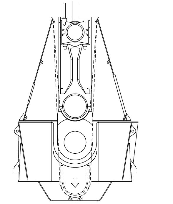
Dismantling of the crankpin bearing
1. Turn the crank to BDC.
2. Suspend two tackles from the lifting brackets,
in the athwartship direction.

3. Turn the crank to TDC.
Mount eye bolts in each side of the crankpin
bearing cap and, using shackles and wire
ropes, hook on the tackles and haul tight.
Loosen the crankpin bearing stud nuts, using
the hydraulic jacks.

4. Lower the bearing cap while seeing carefully
that the studs do not damage the
crankpin journal.
Land the bearing cap on a couple of planks
placed in the oil pan.
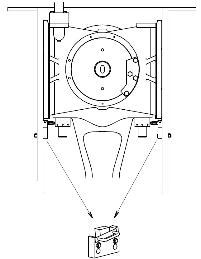
5. If the bearing shell needs to be replaced,
remove the whole bearing cap from the
crankcase.
Hook the tackle onto an eye bolt on one
side of the bearing cap.
Mount the wire guide at the top of the
crankcase door opening.
Using the tackle from the frame box inside
wall, together with a tackle suspended from
the platform bracket, lift the bearing cap out
of the crankcase.

6. Place the bearing cap on one side on a couple of planks.
Inspect the bearing shell. If necessary, dismount the bearing shell
lock screws and replace the bearing shell
by a new one.

7. Turn to TDC.
Mount the four supports for guide shoes on
the crosshead guides.
Carefully turn the crank down until the
guide shoes rest on the supports.
Adjust the support brackets to the guide
shoes so that the weight of the crosshead
is evenly distributed on the four supports.

Note! Normally bearing shells are replaced in
pairs.
If only one of the shells needs replacement.
8. Mount a lifting attachment for securing the
connecting rod at the lower end, on one
side.
Hook on the tackle to a beam under the gallery
platform and haul tight.


11. Dismount the bearing shell lock screws and
lift out the bearing shell.

Mounting of the crankpin bearing
1. Bearing shells of three mm undersize are
available as spares in case of journal rectification. Coat the bearing shell surfaces and the
journal with clean oil.
The excess height X is to ensure the correct
tightening-down of the bearing shell,
and must not be eliminated.


4. Turn the crosshead to TDC. Remove the guide shoe support brackets from the crosshead guides.

5. Suspend the tackles from the lifting brackets
in the top of the frame box.
Lift the bearing cap assembly into the
crankcase and land it on a couple of planks
placed in the oil pan.
6. Hook the tackles onto the wire ropes and
lift the bearing cap into position against the
connecting rod.


Precaution to be taken
Survey to be planned when a sufficient time is available to carry out the same.
Immobilization and permit to work are to be obtained from port authorities. A risk assessment is to be carried out. All involved persons must be familiar with the procedure.
Read manufacturers instruction manual for the correct procedures and clearances.
Keep all special tools, hydraulic jacks, lifting gear ready after an examination and are within the certification.
Turn the engine for at least two revolutions.
Stopped engine
Shut off starting air supply – At starting air receiver
Block the main starting valve
Shut off starting air distributor/distributing system supply
Shut off the control air supply
Engage turning gear
Stop lubricating oil supply
Possible defects
Scoring: It is caused by foreign bodies in the lube oil. Due to bad filtration or because of tin oxide from Corrosion in the bearing from (salt) water contamination that affects bearing and journal.
Pitting: It is usually caused by acidic attack or corrosion. Although spark erosion can be a cause.
Acidity in lube oil can be due to oxidisation, bacterial attack or because the oil has lost its alkalinity reserve. Affects bearing and journal.
Wiping: It Can be partial or complete. It is caused by overheating of the bearing material causing it to melt. This happens due to the breakdown of hydrodynamic film it can be because of overloading,
Water contamination, excessive clearance, lack of oil, low oil viscosity.
Affects bearing with possible scoring of the crankpin.
Ovality: It can be caused due to varying downward load and angularity of control. If ovality exceeds 25% of bearing clearances, hydrodynamic lubrication can be affected. Which affects bearing and journal.
Tests are carried out on completion of the survey
On completion of work, ensure all tools are removed from the crankcase.
Measure and record bearing clearances to ensure that it is within manufacturers limits.
Check oil flow through bearing, without oil the bearing will wipe within seconds.
Turn engine on turning gear for at least 2 revolutions, observing ammeter, comparing with readings taken before. This will ensure there is not a tight spot that may result in failure.
Run the engine for 30 seconds on low load, open crankcase doors and check bearing temperature, and any evidence of white metal in the crankcase.
Repeat after 5 minutes and a 30-minute run. This will highlight any abnormal overheating and may prevent damage to the crankpin should the bearing fail.
After the 30 minute check, the engine load can be gradually increased over a 2 hour period to full load. This will allow the bearing to "bed-in".
Q1. Under Continuous survey of machinery (CSM) bottom end bearing of a large 2stroke slow speed engine is due for the survey;
A. As 2nd engineer, explain the procedure involved in the complete inspection of a bottom end bearing;
B. List the precaution to be taken;
C. Indicate the reasons for possible defects which could be encountered and state how they may be rectified;
D. What tests are carried out on completion of survey and re-assembly.
Q2. A. Describe the procedure for opening a bottom end bearing for inspection making reference to the positioning of the crank and the safety precautions to be observed.
B. State how the bearing clearance may be checked and adjusted when necessary
C. State TWO defects, which may be encountered during inspection of the bottom end bearing and crankpin giving possible causes of EACH.
D. State TWO checks, which should be made before returning the engine to service following an overhaul of the bottom end bearing.
Comments
Post a Comment