
Control and Monitoring Systems
Proportional Plus Integral plus Derivative (PID) control
Split Range Control
Gas Analyzers
Oil in Water Monitor
Oil Mist Detector
Vibration Monitors
An automatically closed-loop system may be defined as a system in which, without human intervention, the actual value of a controlled condition such as level, flow, temperature, viscosity, or pressure is compared with a desired (or set) value representing the required operating condition, with corrective action being taken should a deviation or difference occur between these two values.
The operation of a plant under automatic control in order to control such variables as temperatures level or viscosity etc. is known as Process control.
Feedback is the transmission of a signal representing the controlled condition to comparison with a signal pre-set by the operator, and which is intended to determine the value of the controlled condition. As loose interpretation feedback may consider being similar to the Measured Value.
Open Loop Control means that there is no feedback of information on the controlled condition.
Two-Step (on-off) Control. A simple cheap form of control for use on a process where a considerable deviation from the desired value can be tolerated. With such systems, the desired value is selected and the automatic controller adjusted so that the correcting unit (a valve, pump, or compressor) has only two positions or conditions open/shut, running, or stopped.
Two-Step systems are suitable for processes with high demand-side capacity and a Low Supply-Side capacity, i.e., a large capacity of hot water with a small supply of heat, the reverse would cause oscillation.
Modulating Control or Continuous Control. These are the names given to control systems that provide a continuous and smooth control action and which can be used to eliminate the oscillation that may occur with two-step control if it is necessary to maintain the controlled condition very close to or at the desired value.
Proportional control is the basic form of Modulating control in which the controller is set up so that any change in output is directly proportional to the deviation between the controlled conditions and the desired value. The proportional band of the controller is measured by the percentage of the input range available that is required to make the output signal change over its full range.
Offset: will be discussed in the article at a later stage
Hunting: will be discussed in the article at a later stage
Proportional and Integral control causes the output of the controller at the rate proportional to the deviation between the set value and the measured value. The Inherent problems of Proportional controllers i.e., Hunting and Offset are overcome by the addition of Integral control.
Proportional, Integral and Derivatives controllers cause the output signal change due to this action is proportional to the rate of change of error.
But when two Large capacitors are involved control can become more difficult and it may be necessary to use Cascade control.
The Cascade Control is suitable whenever a system consists of:
(i) More than one thermal capacitor.
(ii) Large mass flow of fluid.
Cascade control comprises two controllers, Master and Slave, the output of Master controller becomes the set value for the slave controller. The slave controller output controls two actuators by split control so that they work in cascade or series and reduce the time lag to a large extent and bring back the steady-state.
Split Range Control
Gas Analyzers
Oil in Water Monitor
Oil Mist Detector
Vibration Monitors
An automatically closed-loop system may be defined as a system in which, without human intervention, the actual value of a controlled condition such as level, flow, temperature, viscosity, or pressure is compared with a desired (or set) value representing the required operating condition, with corrective action being taken should a deviation or difference occur between these two values.
The operation of a plant under automatic control in order to control such variables as temperatures level or viscosity etc. is known as Process control.
Feedback is the transmission of a signal representing the controlled condition to comparison with a signal pre-set by the operator, and which is intended to determine the value of the controlled condition. As loose interpretation feedback may consider being similar to the Measured Value.
Open Loop Control means that there is no feedback of information on the controlled condition.
Two-Step (on-off) Control. A simple cheap form of control for use on a process where a considerable deviation from the desired value can be tolerated. With such systems, the desired value is selected and the automatic controller adjusted so that the correcting unit (a valve, pump, or compressor) has only two positions or conditions open/shut, running, or stopped.
Two-Step systems are suitable for processes with high demand-side capacity and a Low Supply-Side capacity, i.e., a large capacity of hot water with a small supply of heat, the reverse would cause oscillation.
Modulating Control or Continuous Control. These are the names given to control systems that provide a continuous and smooth control action and which can be used to eliminate the oscillation that may occur with two-step control if it is necessary to maintain the controlled condition very close to or at the desired value.
Proportional control is the basic form of Modulating control in which the controller is set up so that any change in output is directly proportional to the deviation between the controlled conditions and the desired value. The proportional band of the controller is measured by the percentage of the input range available that is required to make the output signal change over its full range.
Offset: will be discussed in the article at a later stage
Hunting: will be discussed in the article at a later stage
Proportional and Integral control causes the output of the controller at the rate proportional to the deviation between the set value and the measured value. The Inherent problems of Proportional controllers i.e., Hunting and Offset are overcome by the addition of Integral control.
Proportional, Integral and Derivatives controllers cause the output signal change due to this action is proportional to the rate of change of error.
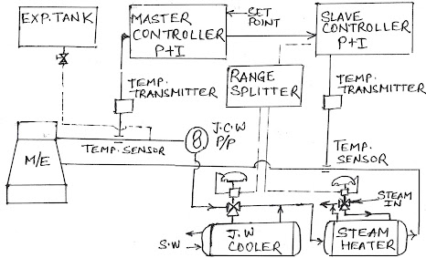
Cascade Control for Jacket Cooling
By suitable adjustment of PID controller, an automatic system can deal with the time lag between a deviation arising and equilibrium being restored.But when two Large capacitors are involved control can become more difficult and it may be necessary to use Cascade control.
The Cascade Control is suitable whenever a system consists of:
(i) More than one thermal capacitor.
(ii) Large mass flow of fluid.
Cascade control comprises two controllers, Master and Slave, the output of Master controller becomes the set value for the slave controller. The slave controller output controls two actuators by split control so that they work in cascade or series and reduce the time lag to a large extent and bring back the steady-state.
Boiler Water Level Control
Modern high pressure, high-performance water tube boilers present a considerable number of problems with regard to the control of water level. The drums are relatively small in size and water capacity but have high outputs, whilst the reaction of the steam and water in the drum to changes in steam demand and hence drum pressure, are complex. A sudden increase in steam demand reduces the steam pressure in the drum, and to drop the temperature of the water to a saturation temperature matching the new pressure, some of the water fleshes off into the steam causing the formation of a mass of steam bubbles which tends to increase the drum level. The situation is aggravated by an increase in evaporation rate due to the increase in the temperature difference (and thus heat transfer rate) due to the drop in saturation temperature between the water in the tubes and the furnace and gas temperature. The effect is known as swell and on a simple level control system would cause the feed control valve to shut in - when in fact it should be opening - making 180 deg. out of phase.When the boiler load levels out, and the combustion system restores the pressure, the saturation temperature also rises, the steam bubble formation (ebullition) drops and the level falls. Comparatively cold incoming feedwater, as the feed valve opens, will cause some steam bubble collapse, and shrinkage of the level can occur. With the small dum of some boilers, this can upset water circulation and cause heating surfaces to be uncovered.
Two Element Control:
To overcome the problem, Two element feedwater control has been devised, this should not be confused with two-term which applies to a Proportional and Integral controller. Here the steam flow is measured by an orifice plate or flow nozzle and working on the basis that for a state of equilibrium feed flow into a boiler must equal steam flow out, the steam flow (the first element of the system) is used to position the feedwater control valve. This valve is characterized so that for a given steam flow signal it is positioned to give a matching feedwater flow.

Three Element Control:
In the previous system, it is necessary to maintain a constant feedwater pressure at the inlet of the regulating valve to optimize operation. Any fluctuation in feed water pressure will affect the drum level and this control will then try to adjust the regulation valve to restore the desired level condition. This could cause cycle conditions in the system, overworking components and compounding the trouble. A third element is therefore introduced, namely, feed flow. Basing the operation upon the fact that for equilibrium steam flow must equally feedwater flow both of these conditions are monitored and the signals compared in a different relay and provided they are equal, the output of this is then added to the desired value of the water level in the drum. This signal is then compared with the drum level measured value signal in the two-term controller and any deviation between the measured value and the desired value plus the difference between the steam and feed flow will cause the controller to reposition the feedwater control valve to restore the level.

Alternate explanation:
This is a three-element two-term water level control. Three elements are water level sensor, steam flow sensor, feed flow sensor. The two terms are Proportional and Integral.
If control is done only through water level sensing, swelling and shrinkage occur, this controller eliminate these problems. During swelling if only a water level sensor is used it will reduce the feed valve and when the boiler consumption stabilizes the water level will fall. During shrinkage, if only a water level sensor is used it will open the feed valve more and when the consumption stabilizes the water level will be high.
Differential relay compares the feed flow and steam flow and gives a signal to the two-term controller. This signal is then compared with the drum level measured value signal in the two-term controller. Any deviation between the measured value and the desired value plus the difference between the steam and feed flow will cause the controller to reposition the feedwater control valve to restore the level.
DP Cell
Differentia1 Pressure cell as shown in Figure. It is employed for remote indication of boiler water level and for supplying a signal for level control systems. For this instrument, tappings are made on the steam and water sides of the boiler Shell and fitted with shut off valves.
Automatic Combustion Control
In order to improve the response of a high capacity boiler plant to the fast changes in loadings whilst maintaining stability, the primary signal to the control loop may be taken from a steam flow sensor/transmitter. This would be in the form of a flow orifice or nozzle, possibly in the boiler saturated steam pipe, with the pressure drop being measured by a differential pressure transmitter in conjunction with a square root extractor to make the output signal (measured value of steam flow) linear, or proportional to steam flow and thus compatible with the other control system signals. This signal is then fed into the computing relay.The steam pressure, either at the drum or superheater outlet, is measured by a steam pressure sensor/transmitter. The output signal from this (measured value of steam pressure) is fed to the master steam pressure controller, a two-term (P + I) controller. Here, this measured value signal is compared with the signal representing the desired value of steam pressure. Any deviation signal is fed into the computing relay. The master steam pressure controller acts as a trimming effect on the firing rate, prevents any prolonged deviation from the desired value steam pressure and overcomes any deficiency in the steam flow signal accuracy which can occur at low loads.
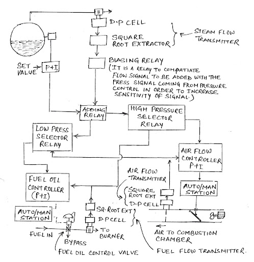
The master signal passing to the fuel flow controller is fed through a low master signal selector where it is compared with the signal representing the airflow. If this master signal is lower, the selector passes it and the two-term controller operates the fuel flow control valves. If the signal is higher, the low signal selector blocks it and there is no change in the signal to these valves.
In the passing to the FD fan two-term controller, via a high signal selector, the master signal is compared with a signal representing fuel flow, and if it is lower than the latter it is blocked, if higher, passed on. The controller then operates the louvre positioner and actuator and/or the fan speed positioner and actuator. Thus, for a rising steam load, the increasing master signal to the fuel oil flow and combustion air controllers is fed first to the high/low signal selectors. At the high signal selector, it is passed on to the FD fan controller which acts to increase the combustion airflow. This increase is detected by an airflow transmitter, the signal output from this being made proportional to airflow by a square root extractor. This signal then acts on the airflow controller, being compared to the new desired value set by the master signal and adjusting the airflow until a balance is achieved. The signal representing airflow is also passed to the low signal selector which, on detecting an increase in combustion air supply to the boiler, switches over to pass the master signal to the fuel oil controller. The master signal then adjusts the desired value of this and so increases the fuel flow. The increase is then measured by a flow orifice, a DP cell and the signal, via a square root extractor, passes to the fuel flow controller where it is compared with the new desired value signal, the output signal then being adjusted to achieve a balance. Fuel to air ratio requirement is fed into the combustion air flow signal from the airflow transmitter. The fuel flow may be controlled by two valves in a split range to give good control over a wide operating range. The combustion airflow may initially be controlled by vanes on the air inlet to the fans and then on fan speed.
Switches may be operated by the steam pressure signal to cut out the steam flow transmitter signal if the safety valve lifting pressure is approached. For a decreasing steam load, the master signal representing the fuel oil requirement is passed initially only to the oil flow controller. Arrangements can be made to prevent the “base” burner from being lost at low oil fuel flow due to controller saturation by means of a cut off relay in the line from the controller to the valve. The figure shows the basis of a burner light-up programme. Conditions that allow or prevent any automatic procedure from continuing are known as 'permissive interlocks, i.e. permission is given or refused to depend upon whether or not a required condition is attained.
Theory of Automatic Control
The operation of a plant under automatic control in order to control such variables as temperature, level, flow viscosity etc., is known as process control. Here we shall take an example see figure, the process is the cooling of lubricating oil in the heat exchange. Working around the system from the process, the controlled condition is the temperature of the lubricating oil, and this is monitored by a sensor or Detecting element, which could be a filled systems thermometer connected to a bourdon tube. This operates a nozzle/flapper device that produces a pneumatic signal, known as the Measured Value, which is directly related to the temperature of the lubricating oil. The operation of this nozzle/flapper amplifier has been explained previously, and it is known in control engineering terms ‘as a Measuring Element, or by some manufacturers as a Transmitter. This measured value signal is taken to a part of the Automatic Controller or Controlling unit.
Here it is compared (one method is shown) with a signal representing the required lubricating oi] operating temperature or the Set Value (set-point) or Desired Value. (There could be a difference between these terms which will be explained later in the text). If the Set Value and Measured Value are the same, the beam will not move, but if there is a difference between these signals, known as the Deviation, or Error, it means that the lubricating oil temperature at the outlet from the cooler is not at the required operating temperature (SetPoint etc.,) and action has to be taken to restore it. The difference in signal pressures on the diaphragms will rotate the beam about the pivot, the movement being the Error Signal and this will operate the Controlling Element.
This develops the signal necessary for the restoration of the oil temperature; the signal may be known as the controller output signal or control signal. This signal is transmitted to the Motor Element or diaphragm of a control valve which then operates the Correcting Element or valve. This then adjusts the Correcting Condition or cooling water flow to enable the oil temperature to be recorded.
feedback is the transmission of a signal representing the controlled Condition for comparison with signal preset by the operator, and which is intended to determine the value of the controlled condition. As a loose interpretation Feedback may be considered to be similar to the Measured Value.
Open Loop Control. This means that there is no feedback of information on the value of the controlled condition of, for example, the lubricating oil in Figure so that the controller has no information on what effect its control of the seawater valve is having on the oil. This form of control can be used and has been used, on some accommodation heating systems. Fans pump air across steam-heated heat-exchangers, into distribution trunking throughout the accommodation. The quantity of steam flowing through the heaters is controlled by a valve, the setting of which is determined by the deck temperature. As long as this temperature remains constant, so will the heat to the air and to the accommodation. However, if the airflow changes (or the steam pressure or temperature) then the air could become cooler or hotter, but the steam valve would remain in the same position as it has no feedback of information on the air temperature.
On-off Control
Two-Step or On-off control is a simple cheap form of control for use on a process where a considerable deviation from the desired value can be tolerated. With such systems, the desired value is selected and the automatic controller adjusted so that the correcting unit (a valve, pump or compressor) has only two positions or conditions open/shut, running or stopped. The automatic controller switches the correcting unit from one extreme to the other as the controlled condition passes the set point. In systems such as temperature control of refrigerated domestic storerooms or steam hot water heaters, there is a time lag between the valve operating and the heat passing into the refrigerator and from the steam to the water due to the heat transfer delay by the tube material; this is known as a Transfer Lag and due to this the store room-temperature or water temperature may take time to rise or fall, as in Figure.
This tends to prevent oscillation. In systems such as domestic freshwater pressure or level control, the operation of the automatic controller, the valve or pump and associated water flow can be very quick and oscillation can occur. Such systems may be given overlap by the use of limit switches or adjusting the controller. The valve or pump then operates at pre-set high level or pressure Values and at pre-set low values.
Two-Step systems are suitable for processes with High Demand Side capacity and Low Supply-Side capacity, i.e., a large capacity hot water tank with a small supply of heat, the reverse would cause oscillation, which can cause rapid wear and tear on components and increased maintenance.
Modulating Control; Continuous Control. These are the names given to control systems that provide a continuous and smooth control action and which can be used to eliminate the oscillation that may occur with two-step control if it is necessary to maintain the controlled condition very close to or at the desired value. The correcting unit, such as a valve, with this form of control can be adjusted to an infinite number of positions between its maximum and minimum limits.
Proportional Control
This is the basic form of modulating control in which the controller is set up so that any change in output is directly proportional to the deviation between the controlled condition and the desired value.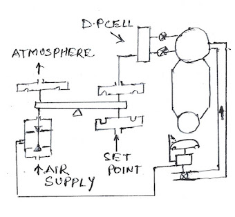

Offset/Droop: When a disturbance occurs to the controlled condition due to a change in plant loading, the correcting unit will have to move to a new position in order to counteract the effect and restore equilibrium, i.e. if the steam demand (see Figure above) increases, the boiler water level will fall and the feedwater inlet valve will have to open to allow more water into the boiler to prevent it eventually emptying. However, the only way. in which the correcting unit (or the feedwater controller valve) can be made to move to a new position in a proportional control system is for an error or deviation to occur, i.e. for the controlled condition (water-level) to move away from the desired value. If the feedwater control valve is therefore initially at a half stroke and has to move to three-quarters stroke, for the water, supply to match the steam demand, then the controller output signal must change by 25 per cent of its range. ( If the output range is 0.2 to 1.0 bar, it must change from 0.6 to 0.8 bar, for example).
If the automatic controller has a proportional band setting of 50 per cent (a gain of 2), then the input signal must alter by 12.5 per cent (i.e. 0.1 bar) to bring about this output change, and hence the boiler water level must fall. If the boiler water level measuring unit has a range of 0-400 mm, then this change in level means a fall of 50 mm. Once equilibrium has been established, the boiler will operate about a new water level 50 mm below The level existing before the increase in steam demand. For each change in steam demand, a new level will exist. The difference between the previous and existing level is known as Offset and sometimes as Steady-State error or Ultimate State error. This offset will remain until a new steam demand causes a change.
Desired Value, Set Value (SetPoint): Confusion can arise over the use of these terms and they are frequently used to indicate the same value. The set vane (setpoint) represents the value of the controlled condition to which the comparing element is set, and is usually the desired value. When using a proportional controller, however, the value of the controlled condition actually obtained in a steady-state, (the control point), differs from this desired value as load changes arise, and this difference is known as the offset. To allow for this, the set value may be adjusted to a value that is different from the desired value. If, for example, in the case of the boiler water level previously discussed, it is necessary to maintain a water level of 100mm in the gauge glass and this is the desired value, then with the load change described, this level drops to 50mm, and there is an offset of 50mm. The operator would then be required to re-adjust the set value to 150 mm for the water level to be controlled at the 100 mm desired value condition.
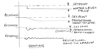
This set point alteration would have to be made with each load change. Such precision of definition is not always used and, in line with most books, Setpoint (value) and desired value will be taken henceforth to be the same. The offset can be reduced by increasing the gain or sensitivity of the controller. This is achieved by adjusting the proportional band setting, reducing or narrowing the band (a lower percentage reading, higher gain reading) and requiring a smaller variation between the measuréd valué and desired value to give an output signal change over the full signal range. In the previous case with a 50 per cent proportional band setting, an input signal change of 0.1 bar brought about an output signal change of 0.2 bar, If this proportional band setting is reduced to 25 per cent (gain of 4) it means that only a quarter of the measured value range has to be used to cause the output signal to change over its complete range, or an input signal change of 0.05 bar brings about an output change of 0.2 bar and opens the valve by 25 per cent.
Thus if the proportional band is narrowed a very small deviation between the measured value and desired value can cause a very large change in the output signal. In the case of the boiler feedwater control valve, a small change in level could cause the valve to open to its full position allowing such an inrush of water that the level would be lifted far above the desired value. As the control system tries to correct this, the valve shuts in and the flow virtually stops. This oscillation or surging effect with rapid opening and closing of the valve is called hunting and should be avoided at all costs as it causes damage to the plant and excessive wear and tears on control and plat equipment. The effect of varying the proportional band is shown in the figure.
Desired Value, Set Value (SetPoint): Confusion can arise over the use of these terms and they are frequently used to indicate the same value. The set vane (setpoint) represents the value of the controlled condition to which the comparing element is set, and is usually the desired value. When using a proportional controller, however, the value of the controlled condition actually obtained in a steady-state, (the control point), differs from this desired value as load changes arise, and this difference is known as the offset. To allow for this, the set value may be adjusted to a value that is different from the desired value. If, for example, in the case of the boiler water level previously discussed, it is necessary to maintain a water level of 100mm in the gauge glass and this is the desired value, then with the load change described, this level drops to 50mm, and there is an offset of 50mm. The operator would then be required to re-adjust the set value to 150 mm for the water level to be controlled at the 100 mm desired value condition.
This set point alteration would have to be made with each load change. Such precision of definition is not always used and, in line with most books, Setpoint (value) and desired value will be taken henceforth to be the same. The offset can be reduced by increasing the gain or sensitivity of the controller. This is achieved by adjusting the proportional band setting, reducing or narrowing the band (a lower percentage reading, higher gain reading) and requiring a smaller variation between the measuréd valué and desired value to give an output signal change over the full signal range. In the previous case with a 50 per cent proportional band setting, an input signal change of 0.1 bar brought about an output signal change of 0.2 bar, If this proportional band setting is reduced to 25 per cent (gain of 4) it means that only a quarter of the measured value range has to be used to cause the output signal to change over its complete range, or an input signal change of 0.05 bar brings about an output change of 0.2 bar and opens the valve by 25 per cent.
Thus if the proportional band is narrowed a very small deviation between the measured value and desired value can cause a very large change in the output signal. In the case of the boiler feedwater control valve, a small change in level could cause the valve to open to its full position allowing such an inrush of water that the level would be lifted far above the desired value. As the control system tries to correct this, the valve shuts in and the flow virtually stops. This oscillation or surging effect with rapid opening and closing of the valve is called hunting and should be avoided at all costs as it causes damage to the plant and excessive wear and tears on control and plat equipment. The effect of varying the proportional band is shown in the figure.
Proportional Plus Reset Control
Two-term Control or Proportional plus Integral Control. The problems of hunting (instability) and offset inherent in the proportional controller can be overcome by using Integral Action or Reset Action added to a proportional controller. Thus, if the characteristics of a particular plant are such that, under proportional control, any attempt to reduce the offset by narrowing the proportional band produces hunting, the proportional band has to be kept wide and reset action added to eliminate the offset effect. The addition of reset action causes the output of the controller to change at a rate proportional to the deviation between the set value and the measured value. In the case of the boiler feedwater control valve, if the water level changes, the controller first generates a signal proportional to the deviation, which moves the feedwater control valve in proportion to the deviation, so that the inflow of water matches steam outflow. Then the reset action is applied at a rate proportional to the deviation so that the valve continues to open, the water inflow exceeding the steam demand, thus restoring the level. As the desired value of the water level is approached, the reset action falls away, the valve starts to close down, until at the desired water level, the reset action disappears and the valve is under Proportional control, Open the required amount so that the steam and water flows are balanced.
Proportional Plus Reset plus Rate control
Proportional Plus Integral plus Derivative Control or Three Term Control. Some plants have an inherent characteristic such that when a disturbance occurs because of the large volumes and in masses or long distances involved, there are long time delays between a disturbance occurring and equilibrium is restored. A lang reset time may be necessary and if there is a tendency to hunting, a wide proportional band will be required. In fact, if the disturbances are frequent, the system may never settle. To improve recovery from a disturbance in a plant with such problems, Derivative or Rate Action may be applied by adding a further term to the automatic controller output, in addition to proportional and reset. Such action tends to stabilize the control system and allows either the proportional band to be narrowed, or a shorter integral action time to be used a combination of both with derivative action time to be used, or a combination of both. With derivative action, the output signal change due to this action is proportional to the rate of change of error. It is measured in terms of Derivative Action Time - the time is taken for the proportional component to become equal to the derivative component under ramp condition. See figure.
Split Range Control
The output signal from a controller may be split into two or more branches to control two or more correcting units.
Gas Analysers
Oxygen:
Reduction of uptake corrosion and monitoring combustion efficiency are two important reasons for checking the oxygen content of boiler uptakes, while gas used for inerting cargo tanks in oil tankers has to be kept to about 3-5 % (alarm at 8 %) to ensure the tank atmosphere is inert.
A number of methods can be used. In the electrochemical type analyser, a high-temperature galvanic cell is used consisting of calcium stabilized zirconium oxide electrolyte with platinum electrodes. These cells require to be heated to about 800°C when the oxygen molecules on the anode (the side of the cell exposed to a high oxygen partial pressure) gain electrons. At the same time, oxygen molecules are formed by reverse action on the cathode.
Output is unaffected by CO, or water and the response is very fast. the e.m.f generated can be used to operate a meter, and a supply of clean dry air is used as a reference.
The magnetic wind type depends on its operation upon the fact that oxygen is rare among gases in that it is paramagnetic, i.e it is attracted by a magnetic field, but the effect is inversely proportional as the square of the oxygen temperature, decreasing rapidly as the temperature increases.
In the filament type shown, two platinum filaments F1 & F2 are mounted in cavities in a metal block, each open to the gas stream being analysed. An electric current heats the filaments which form two arms of a wheat stone bridge. Filament F2 has a magnetic field passed across it, the field only crossing past the filament and its associated heated zone. Thus the oxygen in the gas sample is attracted into the cooler zone of the field, but as it passes across the heater it loses its attraction into the field rapidly and the pressure difference induces a gas flow. This flow of gas cools filament F2 altering the relationship to F1 and unbalancing the Wheatstone Bridge. In turn, a recorder is operated. It is important to maintain constant temperatures and pressures; a 1°C temperature change can give a 1.5 per cent change in reading.
The third type of instrument, the magneto dynamic, is based on two spheres filled with nitrogen which is diamagnetic (repelled by a magnetic field), The spheres are fixed at the ends of a box forming a dumb-bell supported on a torsion bar suspension. The whole-cell operates inside a strong non-uniform magnetic field, the spheres being repelled from the strongest part, rotating the suspension until this force is balanced by the torsion of the suspension. When the oxygen content changes, the force on the dumbbell alters and it takes up a new position. In a practical application, a variable electromagnetic field is used to balance the force on the dumbbell, holding it in zero position and the current to produce this field measures the oxygen content of the gas. A portable version has Lloyds approval.
Carbon Dioxide:
Various types of meters may be used for measuring the CO, content of flue gases and thus ensure that good combustion of the oil in a boiler furnace is taking place. The figure shows a continuous reading type in which platinum wire elements are mounted in two chambers, one the measuring chamber with a gas sample passing through it and the other, the reference chamber, with air passing through it, (In some designs the latter may be sealed:) The elements are usually contained in a heavy block to ensure that the wall-temperatures of the cells are the same. Operation depends upon the relative thermal conductivity of CO2 and air, and the effect this has on the resistance of the elements. The elements are heated to a high temperature relative to the cell walls by an electric current, the circuit forming part of a Wheatstone Bridge. The filtered and dried uniform gas and air flows are drawn across the elements and the difference in thermal conductivity of the CO2 relative to air causes a temperature difference in the wires and hence a change in the wire resistance. This unbalances the Wheatstone Bridge and the degree of unbalance is used to indicate the CO2 present. CO2 has an approximate thermal conductivity of 1 against CO of 4, O2 of 2, N2 of 2 and H20 of 1 (hence the need for drying). Any CO2 or H2 present is recorded as CO2 unless previously removed. In the absorption type, when the gas containing CO2 is brought into contact with a KOH (Potassium Hydroxide) solution, the following reaction takes place:
$\mathrm{CO_{2} + 2KOH \rightarrow K_{2}CO_{3} + H_{2}O}$
The volume of gas remaining will be reduced by a percentage equal to the equal volume percentage of CO2. This type usually involves a filter in the line to a tube containing the liquid. A given volume of gas is pumped into the tube, displacing the air, and then the gas and liquid mix. The change in the level of the liquid is an indication of the volume of CO2 absorbed. Carbon Dioxide recorders also form an essential part of the equipment necessary for the successful carriage of fruit cargoes and other perishable foodstuffs.
Oil in Water Monitor
This is used to check for oil contamination of bilges or ballast water after the separator; also boiler feed water. The device is shown in the Figure produced by Bailey Meters and Controls Ltd, rates on the principle of ultraviolet fluorescence. This is the phenomenon of emission of light from a molecule or atom which has absorbed light of one particular wavelength and re-emits some of this energy at a longer wavelength. A primary light filter allows only the required ultra-violet wavelength into the sample and excludes all others, whilst a secondary or emission filter cuts back this excitation wavelength and accepts only the fluorescent emission wavelength. These wavelengths passing the latter filter are detected by a photo-electric cell. The output of this is a measure of the fluorescence and hence the oil contamination.A sample is taken from the main flow line and passed through a conditioning unit to reduce the dispersed particles to a constant size (5 microns or less) and this ensures the highest efficiency. Flow then continues through a flow control valve to the sensor unit where, if there are any oil particles present, the ultraviolet light causes fluorescence in these. A photoelectric cell then picks up any light present due to the fluorescence of the oil and produces an electrical signal which is thus a function of the oil contamination of the water. In order to prevent dust and condensation from fouling the glass, an air purge is provided, and the mixture passes through the sensor in the form of a falling jet. The instrument has to be calibrated for a particular oil or against a sample of a given oil-water mixture. The monitor is suitable for a wide range of oils and can monitor concentration 0-30 up to 0-6000 ppm depending upon oil type.
Oil Mist Detector (Graviner)
This instrument, shown in Figure, is used to sample the air/oil mixture in a diesel engine crankcase and detect any concentrations due to a hot bearing etc., well below the level at which an explosion may occur. Oil mist is drawn into the instrument by a fan, driven by an electric motor, through sampling tubes connected to the top of the respective crank chambers of the crankcase. A rotating sampling valve, driven off the fan motor, connects each tube in turn for four seconds to the measuring tube, whilst a reference tube has a sample from the remaining crank chambers passing through it so that it can evaluate the difference in oil mist level. The overall mist density of all the crank chambers is also taken once every revolution of the sampling valve and compared with fresh air. A beam of light from a common lamp is reflected by mirrors along the axis of the parallel measuring and reference tubes, energizing silicon photoelectric cells connected electrically back to back so that the output from the circuit is the difference between their individual currents.Under normal conditions the oil mist level is the same in both tebes and the output is zero. An increase in oil mist density in any one crank chamber will unbalance the photo-cell output and at a predetermined level an alarm is energized. A rotating indicator stops at the crank chamber with the abnormal oil mist condition. The lenses and celis should be cleared periodically and the circuits tested daily. The connecting tubes should slope and have no loops to prevent oil blockage. Another version is available in which each crank chamber is compared with a fresh air sample.
Vibration Monitors
Vibration monitoring is being used quite extensively as a means of detecting malfunctioning of rotating machinery at an early stage - long before failure occurs.Two types of measurement are made, the amplitude (i.e displacement velocity or acceleration of the component being monitored) and the frequency at which it occurs. The former gives an indication of the condition and the latter identifies the probable source. Two instruments are used for these purposes. One, as shown in the Figure, is a velocity transducer. It consists basically of a coil surrounding a permanent magnet with the vibration of the machine causing the coil to oscillate relative to the magnet, thus converting the vibration of the machine into an electrical signal. This is proportional to the velocity and can be used to indicate displacement by an integrating amplifier.
The figure shows an accelerometer based on the piezoelectric cell. The instrument comprises a number of discs of piezo-electric crystals beneath a heavy mass. This assembly is then mounted on a heavily sprung loaded base and sealed in a metal case. When vibrated the mass exerts a force on the Piezoelectric discs and these generate an electrical signal directly proportional to the force applied and therefore to the acceleration of the mass. By the use of integrating circuits, velocity or displacement interpretations can be displayed. Piezo-electric cells consist of discs of certain types of crystals such as tourmaline or quartz, which when electrically deformed along certain stress planes produce an electrical potential between opposite faces. Electrodes attached to these faces measure these charges. The crystals give a very rapid response to change in pressure.
Comments
Post a Comment