
Answer EKM Question 19
Fatigue is one of the main causes of crankshaft failure.
1. Sketch and Indicate the most likely location of a fatigue crack;
2. How is a fatigue failure is identified;
3. Describe initiation of a fatigue crack;
4. Sketch and Describe the methods used to inhibit fatigue cracks.
Answer: 1. Fatigue in a material is a measure of its behavior when submitted to cyclical stressing. It may occur as variation of magnitude of stress or a complete reversal. Materials under fatigue may fail at a lower stress value than would be required on the same material under laboratory static stress.
In a crankshaft fatigue crack may originate at the change of cross-section such as at the lip of hole bored in the crankpin. Crack developed in any of the sections crank web, crank-pins and journals which can at times very quickly propagate causing rupture. As a precautionary measure avoid engine operation in critical speed range.
Most likely location of a fatigue crack:

A. Fillet cracks caused by insufficient fillet radius. Fillet radius can be improved by an undercut fillet to improve the radius.
B. The junction of the oil hole meeting the pin surface, if it is abrupt meeting squarely becomes a location of stress concentration and so leads to fatigue cracking around the oil hole. The junction should be rounded off so that the stress lines become continuous.
a. The initial crack may be difficult to detect, but area to check are at the change in section between pin and web and across the web in way of a shrink fit.
b. Crack initiation is hard to find with naked eye hence a closer inspection would reveal a change in metal grain pattern or lines with dark marks indicate initiation of a crack which can be confirmed through a magnifying glass.
c. Crack detection methods such as sprays or ultrasonic may have to be used to confirm suspicions.
d. Random check on crack webs NDT methods will reveal cracks.
e. Checking of the tension of any surrounding blots will indicate a crack if the tension appears to have slackened off.
Fatigue failure in the form of crack appears in 3-stages;
a. Intial crack initiation.
b. Progressive crack growth across the part
c. Final sudden fracture of the remaining cross section
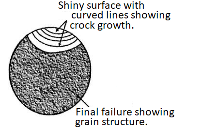
A fatigue failure is easy to identify by looking at the failed section. It will consist of a series of curved visible lines with the surfaces having a polished finish due to movement of the metal surfaces against one another.
The final failure surface will be grained and often at an angle to the original crack.
Fatigue failure is identified as starting at a stress raiser or defect then the crock generated through the material before causing sudden failure. The crack progress is shown as smooth ripped known as striation or beach marks, whilst the sudden failure is of the brittle fracture with the rough appearances.
The initiation side will be where local stress is high enough to increases minute cracks which occur on the metal surface.
The stress can be increased locally by a surface defect or even an extreme stress concentration caused by high applied stress.
4. Describe, with the aid of sketches, the methods used to inhibit fatigue cracks.

Oil holes - these should be minimized whenever possible, and the oil hole opening have wide and smooth radii.
Tensile stresses -fatigue strength is reduced when tensile stress are present, so the radii area are often cold rolled to ensure that the fatigue strength in these area are increased.
Stress applied om harden materials - Fatigue cracks can grow faster when the material is harder, as the dislocations in the metal concentrate the stress on a smaller area of the material structure, hence any hardening of the crank pins must not be applied to the high stressed radii areas.
Crack appearing in fillets are extending up to web may be due to bending fatigue. Complete fracture of a cast steel web may be due to bending fatigue.
Torsion fatigue fracture appear in the crank pin along a plan 45 deg inclined to axis.
Comments
Post a Comment