
Vibration and Forces- Engine Dynamics
Page 10
1. Engine vibration and critical speed
2. Force and Moments in slow speed diesel engine
3. Vibration damper and detuner
4. Static and dynamic loading and balancing in engine
5. Primary and secondary forces and couple
6. Torsional vibration
7. Axial vibration details
8. Purifier vibration reasons
9. Important element in ship vibration
2. Force and Moments in slow speed diesel engine
3. Vibration damper and detuner
4. Static and dynamic loading and balancing in engine
5. Primary and secondary forces and couple
6. Torsional vibration
7. Axial vibration details
8. Purifier vibration reasons
9. Important element in ship vibration
Engine Dynamics
It is critical that vibration is minimized throughout the design and construction stage of any engine installations. The assessment and reduction of vibration are subject to continuous development and research, requiring expert knowledge.
For successful design, vibration behavior calculations are required over the whole operating range of the engine and the propulsion system.
Forces and moments causing vibrations:
Within the engine, various forces and moments are generated by the reciprocating and rotating masses. Often these cyclical forces and moments are neutralized by counterbalancing within the engine. However, if this is not achieved the engine will experience the sum of these forces and moment as external responses, reacting around its own axis and causing vibrations outside of the engine. Vibrations
are problematic, especially if a vibration frequency forces a resonance, causing an amplitude to pass acceptable limits. This section highlights the importance of dynamic consideration, the causes and relevance.
Types of vibration:
• External mass forces and moments
• External lateral forces and moments (Lateral engine vibration or 'rocking')
• Longitudinal engine vibration
• Torsional vibration of the shafting
• Axial vibration of the shafting
• Whirling vibration of the shafting
• Hull vibration
1 External mass forces and moments
The external mass forces and moments are the resulting forces and moments produced by reciprocating and rotating masses of the running gear (i.e. the engine's main oscillating masses) that are transmitted to the surrounding vessel via the foundation. This therefore doesn't consider forces and moments that are produced by combustion forces. The external mass forces and moments depend on the design of a specific engine and the engine speed.
The engine power and tuning has no influence on the external mass forces and moments.

Figure above shows the mass forces and moments generated by the engine. However, where possible these are neutralized. If not, cyclical generation of the external mass forces and moments may lead to unwanted and disturbing vibrations throughout the vessel. This highlights the importance of using countermeasures that balance out the generated mass forces and moments where possible.
1.1 Balancing of mass forces and moments
Forces: With a regular firing order of evenly distributed crank angles, an engine will inherently balance the summation of all vertical (FV) and horizontal (FH) free forces. Sometimes the firing order is designed to be irregular, i.e. unevenly distributed
crank angles, to optimize the overall vibration characteristic of a specific engine type. Regardless, the resulting mass forces are considered to be negligible.
First order moments: First order mass moments ($\displaystyle \mathrm{M_{1V} }$ and $\displaystyle \mathrm{M_{1H} }$ ) can be reduced to acceptable levels by introducing standard counterweights, fitted to the ends of the crankshaft. In special cases non-standard counterweights can be used to reduce either vertical ($\displaystyle \mathrm{M_{1V} }$ ) or horizontal ($\displaystyle \mathrm{M_{1H} }$ ) first order mass moments as required.
Standard counterweights fitted to the ends of the crankshaft reduce the first order mass moments to acceptable limits. However, in special cases non-standard counterweights can be used to reduce either $\displaystyle \mathrm{M_{1V} }$ or $\displaystyle \mathrm{M_{1H} }$ .
Second ($\displaystyle \mathrm{M_{2V} }$ ) and fourth ($\displaystyle \mathrm{M_{4V} }$ ) order vertical mass moments are also generated, although these magnitudes will vary depending on engine type, tuning, and number of cylinders. Unless a problematic vessel design leads to unfavourable vibration, there is normally no cause for concern for engines with 7 cylinders or more. However, 5 and 6-cylinder engines are known to generate high magnitudes of unbalanced second order vertical mass moments ($\displaystyle \mathrm{M_{2V} }$ ) and should therefore
be carefully considered. Consequently, for 5 and 6-cylinder engines it is strongly recommend that the impact of the second order vertical mass moment on the vessel is carefully checked. In cases where the investigation reveals a possible problem, It is recommend to consider the installation of one of the following countermeasures, designed to reduce the effects of second order vertical mass moments to acceptable values.
1.2 Countermeasure for second order vertical mass moments
Electrically driven compensator (external compensator)
If disturbing second order vibrations occur on 5 and 6-cylinder engines, it is strongly recommend that an electrically driven compensator is fitted or retrofitted to the ship’s structure. As seen in Figure, such a compensator is usually
installed in the steering gear compartment. It is tuned to the engine operating speed and controlled accordingly.

This countermeasure should also be considered for other cylinder number engines if the second order vertical mass moments ($\displaystyle \mathrm{M_{2V} }$ ) surpass the necessary limits. However, suitability will vary for different engines and vessel design.
Power related unbalance
The power related unbalance (PRU) values can be used to estimate the risk of unacceptable levels of hull vibrations caused by external mass moments of first and second order. The PRU is calculated with the following formula:
$\displaystyle \mathrm{PRU =\frac{M_x(Nm)}{Engine\ Power (kW)} }$
where:
PRU = power related unbalance
$\displaystyle \mathrm{M_{x} }$ = $\displaystyle \mathrm{M_{2V} }$ (typically), $\displaystyle \mathrm{M_{1H} }$ & $\displaystyle \mathrm{M_{1V} }$ (considered as well)
The $\displaystyle \mathrm{M_{x} }$ and the resulting PRU values of an engine are dependent on the number of cylinders and tuning option.
2 External lateral forces and moments
The external lateral forces and moments (lateral engine vibrations resulting in ‘rocking’) are generated by the combustion process and to a small extent by the reciprocating masses of the running gear. The lateral forces depend on the CMCR, tuning, and engine speed.

The forces between the piston and the connecting rod reaction cause a lateral force to act on the crosshead guide rails. The lateral forces at the guide rails are transmitted to the engine block and to the foundation.
The resulting lateral forces and moments may excite resonances of the combined engine and foundation system. In addition, hull resonances or local vibrations in the engine room may be generated.
Lateral vibration types
The resulting lateral forces and moments generate two different modes of lateral engine vibration, the H-type and X-type vibration.
H-type vibration
H-type lateral vibrations are characterised by a mode shape where both sides of the top of the engine, the driving and free end, vibrate together, in phase. The lateral guide forces ($\displaystyle \mathrm{F_{L} }$ ) result in a lateral moment, expressed as resulting lateral H-type
moment ($\displaystyle \mathrm{M_{LH} }$ ).

X-type vibration
X-type lateral vibrations are characterised by a mode shape where at the top of the engine, the driving and free ends vibrate in counter-phase to each other. As these resulting lateral guide forces create opposing axial moments at the two ends of the engine, the X-type lateral vibrations are expressed as a moment around the vertical axis, the resulting lateral X-type moment ($\displaystyle \mathrm{M_{LX} }$ ).
2.2 Reduction of lateral vibration
The amplitudes of the vibrations transmitted to the hull depend on the design of engine seating, frame stiffness and exhaust pipe connections. As the amplitude of the vibrations cannot be predicted with absolute accuracy, the support to the ship’s structure and the space needed to install stays should be considered in the early design stages of the engine room structure. This is true for both lateral and longitudinal vibrations.
Lateral hydraulic stays:
If needed, lateral stays must be fitted between the upper engine platform and the ship hull to avoid harmful resonance conditions. The main effect of lateral stays is to shift the resonance frequency sufficiently above nominal speed. In addition,
some damping effect is provided by the hydraulic stays. Such hydraulic stays can be either for both-side or one-side installation.
• Hydraulic stays for one-side installation have two oil chambers (one on each side of the piston) and provide in this regard a ‘damping effect’ in both directions.
• Hydraulic stays for both-side installation have an oil chamber on one side of the piston and an air chamber on the other side. The air chamber provides little to no damping effect.

A stiff engine foundation design is recommended in the longitudinal and lateral directions, as this is always best practice in minimising hull vibrations.
Electrically driven compensator
If lateral stays cannot be installed, the following can be used to reduce lateral engine
vibrations:
• For H-type mode, one electrically driven compensator can be installed on the upper platform in the longitudinal centre point of the engine. This reduces the lateral engine vibrations and the effect on the ship’s superstructure.
Alternatively, two compensators, one fitted at each end of the engine upper platform, can be applied, synchronised in phase.
• For X-type vibration, two compensators, one fitted at each end of the engine upper platform, are necessary and are synchronised in counter-phase. It must be noted that electrically driven compensators can only compensate one
harmonic excitation frequency at a time.
Strong axial vibrations in the shafting, transmitted from the thrust bearing to the engine structure and foundation, can excite inadmissible longitudinal vibrations at the engine top and as a consequence in the superstructure. In any case, to prevent such vibrations, the double-bottom structure should be as stiff as possible in the longitudinal direction.
Reduction of longitudinal vibration (5-cylinder engines)
In general, longitudinal stays are only especially needed on 5-cylinder engines when a shafting layout has a main torsional critical speed above the nominal speed, resulting in strong longitudinal engine vibrations at the top of the engine block. This tends to only occur by using intermediate shafts with oversized diameters, which is no longer common today.
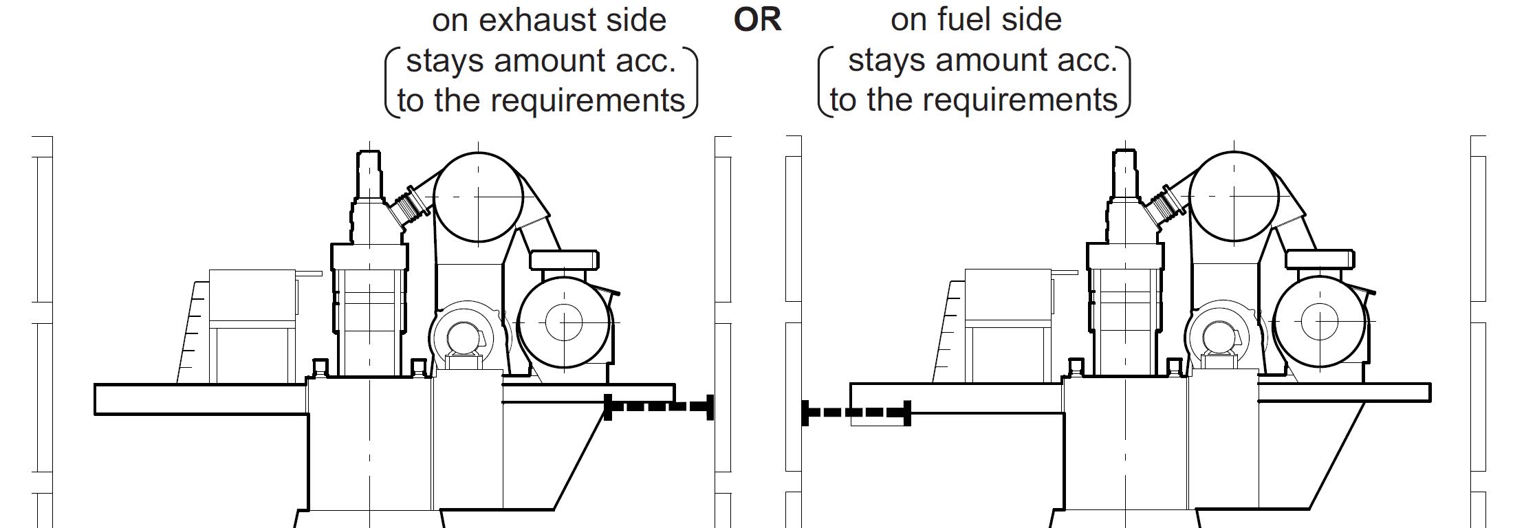
Longitudinal stays to prevent vibration in superstructure:
However, there can be installations where it might be beneficial to install longitudinal stays. This is not because of inadmissible longitudinal vibrations at the engine top but because of possible disturbing longitudinal vibrations in the superstructure, close to nominal speed. By fitting longitudinal stays the disturbing resonance can be shifted above nominal speed.
The decision if longitudinal stays are needed or not has to be made by the shipyard based on a global ship vibration investigation, or on vibration measurements taken at the top of the engine block and in the superstructure (on the first
vessel of a series).
They are arranged as shown in Figure.

The following types of longitudinal stays can be applied:
Hydraulic type stays:
Hydraulic stays can be installed to either the free end or the driving end side of the engine according to the design and requirements of makers.
Friction stays: They can be installed according to maker, to either the engine free end or driving end side.
The layout of friction type stays must conform to the drawing ‘Engine stays / friction type’ and the associated friction stays drawings. Deviations are not acceptable, especially the friction coefficient of the shim and the disc spring properties, which must follow exact specification.
Torsional vibrations are generated by gas and inertia forces as well as by the irregularity of the propeller torque. It does not cause hull vibration (except in very rare cases) and is not perceptible in service, but produces additional dynamic stresses in the shafting system.
The shafting system comprises of the crankshaft, propulsion shafting, propeller, engine running gear, flexible couplings, and power take-off (PTO). The complete assembly of the shafting system must be considered when determining the torsional loads in the system components.
Torsional vibration calculation (TVC):
The torsional loads in the system components are determined by performing a torsional vibration calculation (TVC). The TVC must be done in the early stage for every project.
Across the engine's speed range, all system components must remain within their corresponding torsional vibration load limits. If in a component, the torsional loads exceed the corresponding limit, appropriate countermeasures have to be
applied.
The calculation normally requires approval by the relevant classification society and may require verification by measurement on board ship during sea trials. All data required for torsional vibration calculations should be made available to the engine supplier in an early design stage.
Barred speed range (BSR):
At a certain speed range the torsional vibration stresses in the shafting may exceed the limits for continuous operation. If this occurs, a barred speed range (BSR) must be defined. The width of the BSR is defined by the classification society.
The BSR must be passed through rapidly and some classification societies have defined rules about the maximum permissible passage time through the BSR. In general, the target is to have a maximum passage time of 30 seconds.
In order to guarantee a rapid passage of the BSR, a minimum power margin of 10 % at the upper boundary of the BSR must be present. The power margin is defined as the margin between the bollard pull curve and the engine torque limit.
In any case, within the BSR the torsional shaft stress must not exceed the transient limit, otherwise other appropriate countermeasures have to be taken.
4.1 Reduction of torsional vibration
Excessive torsional vibration can be reduced by optimising the shaft diameters, selecting a different (heavier) flywheel, adding a front disc (tuning wheel) to the free end of the crankshaft or adding a torsional vibration damper to the free end of the crankshaft. A torsional vibration damper reduces the torsional stresses by absorbing part of the vibration energy.
Low-energy vibrations
Viscous damper Where low-energy torsional vibrations have to be reduced, a viscous damper can be installed. In some cases, the torsional vibration calculation shows that an additional oil-spray cooling for the viscous damper is needed. In
such cases the layout must be in accordance with the recommendations of the
damper manufacturer. The viscosity of the silicone oil in the viscous damper must be checked periodically. The interval is specified by the damper manufacturer.
High-energy vibrations:
For high-energy torsional vibrations that may occur e.g. on 5 and 6-cylinder engines, a spring type damper with its tuning and damping effect may be considered;
Spring damper: The spring type damper must be supplied with oil from the engine’s lubricating oil system. Depending on the torsional vibration energy to be absorbed, it can dissipate up to 50 kW energy (depends on number of cylinders).
The oil flow to the damper is approx. 12 m^3/h. An accurate value will be given after the results of the torsional vibration calculation are known.
For spring type damper installation, the application of a damper monitoring system is mandatory.

4.2 PTO/PTI systems effect on torsional vibration:
A propulsion plant may include a main-engine driven generator (PTO, power take-off), a shaft-line connected electric motor (PTI, power take-in), or both. These elements are connected to the engine or shafting by clutches, gears, shafts and/or elastic couplings.
Installations with PTO or PTI require special attention in the early stages of a project. These systems may cause torsional vibrations and alignment challenges.
Risk of instable engine speed:
For many PTO / PTI systems that use elastic couplings, the lowest torsional natural frequency can be problematic if it is below approximately 1.5 Hz. Here, there is a risk of engine speed instability where the engine constantly adjusts its speed to compensate the rotating vibration; this must be considered and compensatedfor in the engine speed control system.
Installation of MFD: In addition, such PTO / PTI systems are very sensitive to misfiring as varying firing loads can cause inadmissible torsional vibrations. To protect the elastic couplings and gears from any misfiring, a misfiring detection device (MFD) must be installed. This indicates either partial or total misfiring, allowing for appropriate countermeasures (e.g. speed reduction, de-clutching of PTO / PTI branch) to be applied automatically, protecting the PTO / PTI components.
5. Axial vibration:
The axial vibrations mainly depend on the dynamical axial system of the crankshaft, the mass of the torsional vibration damper, and any free-end installations or flywheel fitted to the crankshaft. Additionally, axial vibrations can be considerably
influenced by torsional vibrations. This influence is called coupling effect.
It is recommended that axial vibration calculations are carried out at the same time as torsional vibration calculations. To consider the coupling effect of torsional vibrations on axial vibrations, it is necessary to apply a suitable coupled
axial vibration calculation method.
As the shafting system is made up of masses and elastic connections, it is capable of vibrating and resonating at several frequencies. This would result in excessive stress in the crankshaft and in some cases can lead to excessive vibration of the
upper part of the engine.
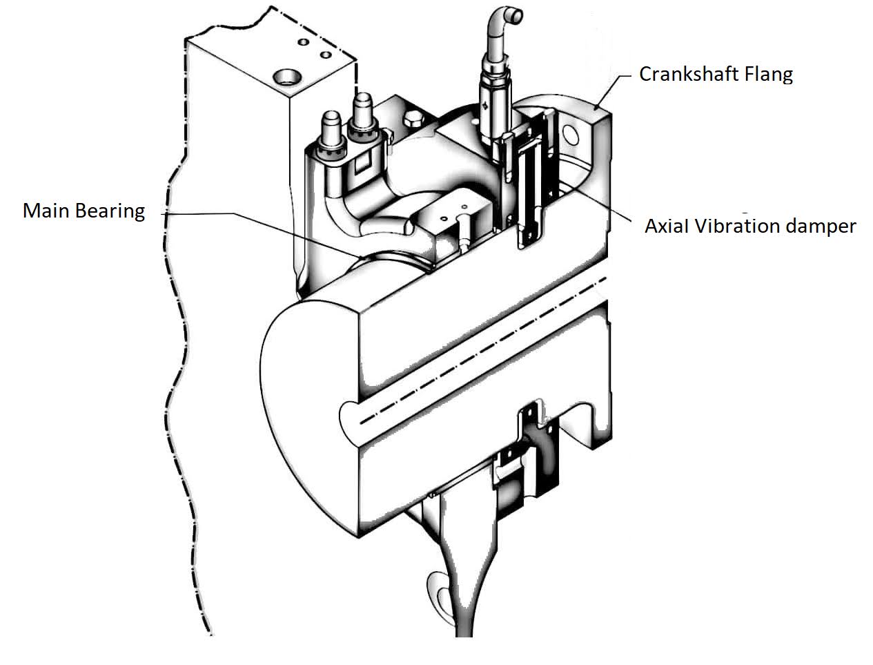
Reduction of axial vibration:
Axial vibration damper: To limit the influence of axial excitations and reduce the level of vibration, engines are equipped with an integrated axial vibration damper.
In most cases, this lowers the axial vibrations in the crankshaft to acceptable values, meaning no further countermeasures are required. No excessive axial vibrations occur, neither in the crankshaft, nor in the upper part of the engine.
The integrated axial vibration damper is mounted at the free end of the crankshaft. It is connected to the main lubricating oil circuit. An integrated oil pressure monitoring system continuously checks the correct operation of the axial vibration
damper.
6 Whirling vibration
Whirling vibrations are generated when the shaft rotates and goes into transverse oscillations. If the shaft is out of balance, the resulting centrifugal forces will induce the shaft to vibrate. This vibration is commonly known as whirling vibration, bending vibration or lateral shaft vibration.
Whirling vibrations are in most cases not relevant in propulsion shafting with directly coupled low-speed 2-stroke engines. Typically, whirling vibrations are only relevant in 2-stroke installations having a very long shaft line (longer than
60 m).
Many classification societies do not require whirling vibration calculations for installations with low-speed 2-stroke engines. In general, only the natural whirling frequencies are calculated. The number and position of the shaft bearings have a significant influence on the natural frequencies. As such, the whirling vibration calculation must be performed after or together with the alignment calculation.
7 Hull vibration
The hull and accommodation area are susceptible to vibration caused by the propeller, machinery and sea conditions. Controlling hull vibration from engine excitation is achieved by a number of different means and may require the fitting of
second order mass moment compensators, lateral / longitudinal stays, electrical H-type or X-type compensators and/or torsional vibration dampers.
Avoiding problematic hull vibrations cannot be achieved in isolation and requires consideration and cooperation from propeller manufacturer, naval architect, shipyard, and engine builder.
8 Countermeasures for dynamic effects
8.1 External mass moments and vibrations
The following tables indicate where dynamic effects and the countermeasures required to reduce them are to be given special attention.
8.1 External mass moments and vibrations
The following tables indicate where dynamic effects and the countermeasures required to reduce them are to be given special attention.
Table-1 Countermeasures for external mass moments
Table-2 Countermeasures for lateral and longitudinal vibrations
A = The countermeasure indicated is needed.
B = The countermeasure indicated may be needed and provision for the corresponding countermeasure is recommended.
C = The countermeasure indicated is not needed.
a) ‘A’ for installations having the main torsional critical above nominal speed (installations with increased shaft diameters)
Table-2 Countermeasures for lateral and longitudinal vibrations
B = The countermeasure indicated may be needed and provision for the corresponding countermeasure is recommended.
C = The countermeasure indicated is not needed.
a) ‘A’ for installations having the main torsional critical above nominal speed (installations with increased shaft diameters)
Table 6-3 Countermeasures for torsional and axial vibrations of the shafting
Comments
Post a Comment