
Answer MET Question 2
Question: A. Explain the methods used to control the speed of a 3 Phase induction motors.
B. Draw and Explain a Variable Frequency Drive used
for optimization of energy efficiency of auxiliary machineries on board
vessels.
Answer:- Speed Control of Induction Motors
A
3-phase induction motor is practically a constant-speed machine, more
or less like a d.c. shunt motor. The speed regulation of an induction
motor (having low resistance) is usually less than 5% at full-load.
However, there is one difference of practical importance between the
two. Whereas d.c. shunt motors can be made to run at any speed within
wide limits, with good efficiency and speed regulation, merely by
manipulating a simple field rheostat, the same is not possible with
induction motors. In their case, speed reduction is accompanied by a
corresponding loss of efficiency and good speed regulation. That is why
it is much easier to build a good adjustable-speed d.c. shunt motor than
an adjustable speed induction motor. Different methods by which speed
control of induction motors is achieved, may be grouped under two main
headings
1. Control from stator side
(a) by changing the applied voltage
(b) by changing the applied frequency
(c) by changing the number of stator poles
2. Control from rotor side
(d) rotor rheostat control
(e) by operating two motors in concatenation or cascade
(f) by injecting an e.m.f. in the rotor circuit.
A brief description of these methods would be given below
(a) Changing Applied Voltage
This method, though the cheapest and the easiest, is rarely used because
(i) a large change in voltage is required for a relatively small change in speed
(ii)
this large change in voltage will result in a large change in the flux
density thereby seriously disturbing the magnetic conditions of the
motor.
(b) Changing the Applied Frequency
This
method is also used very rarely. We have seen that the synchronous
speed of an induction motor is given by $\displaystyle \small
\mathrm{N_s = \frac{120f}{P}}$ . Clearly, the synchronous speed (and
hence the running speed) of an induction motor can be changed by
changing the supply frequency 'f'. However, this method could only be
used in cases where the induction motor happens to be the only load on
the generators, in which case, the supply frequency could be controlled
by controlling the speed of the prime movers of the generators. But,
here again the range over which the motor speed may be varied is limited
by the economical speeds of the prime movers. This method have been
used to some extent on electrically-driven ships.
(c) Changing the Number of Stator Poles
This
method is easily applicable to squirrel-cage motors because the
squirrel-cage rotor adopts itself to any reasonable number of stator
poles. From the above equation it is also clear that the synchronous
(and hence the running) speed of an induction motor could also be hanged
by changing the number of stator poles. This change of number of poles
is achieved by having two or more entirely independent stator windings
in the same slots. Each winding gives a different number of poles and
hence different synchronous speed. For example, a 36-slot stator may
have two 3-ф windings, one with 4 poles and the other with 6-poles. With
a supply frequency of 50-Hz, 4-pole winding will give $\displaystyle
\small \mathrm{N_s = \frac{120\times 50}{4}}$ = 1500 r.p.m. and the 6-
pole winding will give $\displaystyle \small \mathrm{N_s =
\frac{120\times 50}{6}}$ = 1000 r.p.m. Motors with four independent
stator winding are also in use and they give four different synchronous
(and hence running) speeds. Of course, one winding is used at a time,
the others being entirely disconnected.
This method has been used for elevator motors, traction motors and also for small motors driving machine tools.
Speeds
in the ratio of 2:1 can be produced by a single winding if wound on the
consequent-pole principle. In that case, each of the two stator
windings can be connected by a simple switch to give two speeds, each,
which means four speeds in all. For example, one stator winding may give
4 or 8-poles and the other 6 or 12-poles. For a supply frequency of
50-Hz, the four speeds will be 1500, 750, 1000 and 500 r.p.m. Another
combination, commonly used, is to group 2- and 4-pole winding with a 6-
and 12-pole winding, which gives four synchronous speeds of 3000, 1500,
1000 and 500 r.p.m.
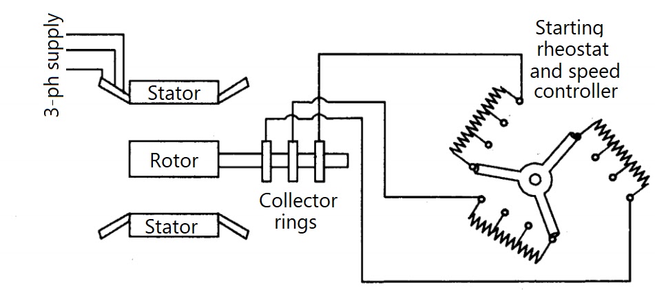
(d) Rotor Rheostat Control
In
this method, which is applicable to slip-ring motors alone, the motor
speed is reduced by introducing an external resistance in the rotor
circuit. For this purpose, the rotor starter may be used, provided it is
continuously rated. This method is, in fact, similar to the armature
may be used, provided it is continuously rated. This method is in fact,
similar to the armature rheostat control method of d.c. shunt motors.
It
is well known that near synchronous speed (i.e. for very small slip
value), $\displaystyle \small \mathrm{T \alpha \frac{s}{R_2}}$ . It is
obvious that for a given torque, slip can be increased i . e speed can
be decreased by increasing the rotor resistance $\displaystyle \small
\mathrm{R_2}$ .
One
serious disadvantage of this method is that with increase in rotor
resistance, R losses also increase which decrease the operating
efficiency of the motor. In fact, the loss is directly proportional to
the reduction in the speed. The second disadvantage is the double
dependence of speed, not only on $\displaystyle \small \mathrm{R_2}$
but on load as well.
Because of the wastefulness of this method, it is used where speed changes are needed for short periods only.
(e) Cascade or Concatenation or Tandem Operation
In
this method, two motors are used and are ordinarily mounted on the
same shaft, so that both run at the same speed (or else they may be
geared together). The stator winding of the main motor A is connected to
the mains in the usual way, while that of the auxiliary motor B is fed
from the rotor circuit of motor A . For satisfactory operation the main
motor A should be phase-wound i.e. of slip-ring type with stator to
rotor winding ratio of 1:1, so that, in addition to concatenation, each
motor may be run from the supply mains separately. There are at least
three ways (and some-times four ways) in which the combination may be
run.

1.
Main motor A may be run separately from the supply. In that case, the
synchronous speed is $\displaystyle \small \mathrm{N_{sa} =\
\frac{120f}{P_a}}$ where $\displaystyle \small \mathrm{P_a}$ = Number
of stator poles of motor A .
2.
Auxiliary motor B may be run separately from the mains (with motor A
being disconnect.). In that case, synchronous speed is $\displaystyle
\small \mathrm{N_{sb} =\ \frac{120f}{P_b}}$ where $\displaystyle \small
\mathrm{P_a}$ = Number of stator poles of motor B.
3.
The combination may be connected in cumulative cascade i.e. in such a
way that the phase rotation of the stator fields of both motors is in
the same direction. The synchro-nous speed of the cascaded set, in this
case, is N„ = 120 fl(Pa+
When
the cascaded set is started, the voltage at frequency/ is applied to
the stator winding a machine A. An induced e.m.f. of the same frequency
is produced in rotor A which is supplied to auxiliary motor B. Both the
motors develop a forward torque.A the shaft speed rises, the rotor
frequency of motor A falls and so does the synchronous speed of motor B.
The set settles down to a stable speed when the shaft speed becomes
equal to the speed of rotating field of motor B.
Considering
load conditions, we find that the electrical power taken in by stator A
is partly used to meet its and core losses and the rest is given to its
rotor. The power given to rotor is further divided into two parts one
part, proportional to the speed of set i.e. 'N' is converted into
mechanic power and the other part proportional to $\displaystyle \small
\mathrm{N_{sa}-N}$ is developed as electrical power at the slip
frequency, and is passed on to the auxiliary motor B, which uses it for
producing mechanical power and losses. Hence, approximately, the
mechanical outputs of the two motors are in the ratio $\displaystyle
\small \mathrm{N:(N_{sa}-N)}$ . In fact, it comes to that the mechanical
outputs are in the ratio of the number of poles of the motors.
(f)
Injecting an e.m.f. in the Rotor Circuit
In this method, the speed of an induction motor is controlled by
injecting a voltage in the rotor circuit, it being of course, necessary
for the injected voltage to have the same frequency as the slip
frequency. There is, however, no restriction as to the phase of the
injected e.m.f.
When we insert a voltage which is in phase opposition to the induced
rotor e.m.f., it amounts to increasing the rotor resistance, where as
inserting a voltage which is in phase with the induced rotor e.m.f., is
equivalent to decreasing its resistance. Hence, by changing the phase of
the injected e.m.f. and hence the rotor resistance, the speed can be
controlled..

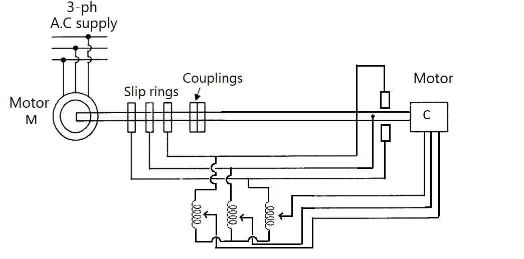
One such practical method of this type of speed control is Kramer system, as shown in figure above, which is used in the case of large motors of 4000 kW or above. It consists of a rotary converter which converts the low-slip frequency a.c. power into d.c. power which is used to drive a d.c. shunt motor, mechanically coupled to the main motor. The main motor is coupled to the shaft of the d.c. shunt motor. The slip-rings of main motor are connected to those of the rotary converter. The d.c. output of rotary converter is used to drive d.c motor. Both rotary converter and d.c motor are excited from the d.c. bus-bars or from an exciter. There is a field regulator which governs the back e.m.f. , of d.c motor and hence the d.c. potential at the commutator of rotary converter which further controls the slip-ring voltage and therefore, the speed of main motor. One big advantage of this method is that any speed, within the working range, can be obtained instead of only two or three, as with other methods of speed control. Yet another advantage is that if the rotary converter is over-excited, it will take a leading current which compensates for the lagging current drawn by main motor and hence improves the power factor of the system.
Comments
Post a Comment