
Answer MET Question 45
Question : A sketch a circuit diagram for an automatic voltage regulator
illustrating how the AVR utilizes a silicon-controlled rectifier to
control the excitation system for an alternator. 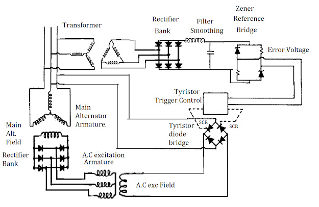 The
terminal volatge is sensed by a 3-ph star-delta stepdown transfoemer
and rectifier to D.C by a 3-ph bridge rectifier bank and smoothen by L-C
filter to represent the actual terminal voltage in a reduced D.C form.
The
terminal volatge is sensed by a 3-ph star-delta stepdown transfoemer
and rectifier to D.C by a 3-ph bridge rectifier bank and smoothen by L-C
filter to represent the actual terminal voltage in a reduced D.C form.
This voltage is compaired in a zener reference brodge circuit with the desired voltage provided by the zener breakdown voltage so that the output gives the error or deviation between the two ( voltage difference between actual and desired value).
This error voltage is utilised for the thyristor trigger control in the diode bridge. This thyristor diode bridge is provided with an A.C supply and the output depends on the conduction period of the thyristor which is triggered by the error voltage as mentioned earlier.
The output from the thyristor diode bridge goes to the A.C exciter field of the alternator which inturn includes A.C voltage in A.C exciter 3-ph armature winding. This voltage is rectified by a bridge rectifier mounted on rotor shaft and finally provides excitation for main alternator field winding. This will generate 3-ph A.C voltage in the main armature winding.
Answer:

This voltage is compaired in a zener reference brodge circuit with the desired voltage provided by the zener breakdown voltage so that the output gives the error or deviation between the two ( voltage difference between actual and desired value).
This error voltage is utilised for the thyristor trigger control in the diode bridge. This thyristor diode bridge is provided with an A.C supply and the output depends on the conduction period of the thyristor which is triggered by the error voltage as mentioned earlier.
The output from the thyristor diode bridge goes to the A.C exciter field of the alternator which inturn includes A.C voltage in A.C exciter 3-ph armature winding. This voltage is rectified by a bridge rectifier mounted on rotor shaft and finally provides excitation for main alternator field winding. This will generate 3-ph A.C voltage in the main armature winding.
The current fed by AVR to the Excitor Stator should be DC current(and not AC current) then only it can produce a permanent magnetic field which thereby produces EMF to the Excitor Rotor to produce AC current.
ReplyDelete