Answer MET Question 47
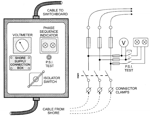
Question : With reference to the provision of a shore electrical supply to a ship: A. Sketch an arrangement for taking A.C. shore supply and checks to be carried out prior Taking shore connection? B. Describe the method of safely connecting the arrangement sketched in (A) to the shore Supply?
Answer:
A.
A shore-supply is required so that the ship's generators and their
prime-movers can be shut down for major overhaul during a dry-docking
period. There must be a suitable connection box conveniently located to
accept the shore supply cable. The connection box
is often located at the entrance to the accommodation or in the emergency generator room.
The connection box must have suitable terminals to accept the shore supply cable, including an earthing terminal to earth the ship's hull to the shore earth.
The connection box must have a circuitbreaker or an isolator switch and fuses to protect the cable linking the connection box to the main switchboard, with a data plate giving details of the ship's electrical system (voltage and frequency) and showing the method for connecting the shore supply cable.
A voltmeter is fitted to indicate polarity of. a d.c. shore supply.
For an a.c. shore supply a phase-sequence indicator is fitted to indicate correct supply phase sequence. This indicator may be arranged as two lamps connected as an unbalanced load across the three phases via resistors and capacitors. The sequence is "right" (or correct) when the right side lamp is bright and the other is dark.
An alternative P.S.I. indicator is a rotary pointer driven by a small 3-phase induction motor.
At the main switchboard an indicator is provided, usually a lamp, to indicate that the shore supply is available for connection to the bus-bars via a connecting switch or circuit-breaker.
B.
It is not normally possible to parallel the shore supply with the
ship's generators. The ship's generators must, therefore, be
disconnected before the shore supply can be connected to the main
switchboard. Normally, the shore supply switch on the main switchboard
is interlocked with the generator circuit breakers so that it cannot be
closed if the generators are still connected.
First the earthing connection is made. Then the three phase supply cable are connected to the given terminals in correct phase sequence(red-yellow-blue).
First the earthing connection is made. Then the three phase supply cable are connected to the given terminals in correct phase sequence(red-yellow-blue).
A
reversed phase sequence (red-blue-yellow) will produce a reversed shaft
rotation in all 3-phase motors because the direction of their rotating
magnetic fields will be reversed with disastrous results. This fault is
remedied by interchanging any two conductors of the shore supply cable
at the connection box.
The shore supply may have a different frequency and/or voltage to that of the ship's system. A higher frequency will cause motors to run faster, be overloaded and overheat. A higher voltage will generally cause equipment to take excess current and overheat. It will also cause motors to accelerate more rapidly and this may over-stress the driven loads.
A lower voltage is generally not so serious but may cause motors to run slower and overheat, and may cause motors to stall.
If the shore supply frequency differs from the ship's normal frequency then, ideally, the shore supply voltage should differ in the same proportion.


Comments
Post a Comment